TERMINALS OF ECU
FORWARD RECOGNITION CAMERA
NOTICE:
- DTCs may be output when connectors are disconnected during inspection. Therefore, be sure to clear the DTCs using the Techstream once the inspection has been completed.
- Do not apply excessive force to the forward recognition camera connector.
(a) Check forward recognition camera

|
Terminal No. (Symbol) |
Wiring Color |
Terminal Description |
Condition |
Specified Condition |
|---|---|---|---|---|
|
F46-7 (IGB) - Body ground |
BE - Body ground |
Power source |
Ignition switch ON |
11 to 14 V |
|
Ignition switch off |
Below 1 V |
|||
|
F46-10 (GND) - Body ground |
W-B - Body ground |
Ground |
Always |
Below 1 Ω |
|
F46-5 (CA1P) - Body ground |
L - Body ground |
CAN communication signal |
Ignition switch ON |
Pulse generation (Waveform 1) |
|
F46-11 (CA1N) - Body ground |
W - Body ground |
Pulse generation (Waveform 2) |
||
|
F46-6 (CANH) - Body ground |
B - Body ground |
Pulse generation (Waveform 1) |
||
|
F46-12 (CANL) - Body ground |
W - Body ground |
Pulse generation (Waveform 2) |
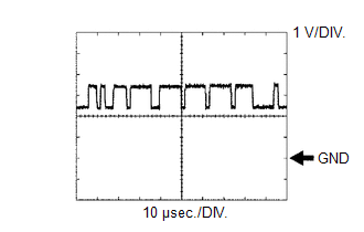
(b) WAVEFORM 1
(1) CAN communication signal
|
Item |
Content |
|---|---|
|
Terminal Name |
Between F46-5 (CA1P) and F46-10 (GND) Between F46-6 (CANH) and F46-10 (GND) |
|
Tester Range |
1 V/DIV., 10 μsec./DIV. |
|
Condition |
Ignition switch ON |
HINT:
The waveform varies depending on the CAN communication signal.
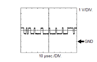
(c) WAVEFORM 2
(1) CAN communication signal
|
Item |
Content |
|---|---|
|
Terminal Name |
Between F46-11 (CA1N) and F46-10 (GND) Between F46-12 (CANL) and F46-10 (GND) |
|
Tester Range |
1 V/DIV., 10 μsec./DIV. |
|
Condition |
Ignition switch ON |
HINT:
The waveform varies depending on the CAN communication signal.