Toyota Tacoma (2015-2018) Service Manual: Television Camera
Components
COMPONENTS
ILLUSTRATION
Installation
INSTALLATION
PROCEDURE
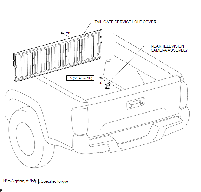
1. INSTALL REAR TELEVISION CAMERA ASSEMBLY
(a) Install the rear television camera assembly with the 2 bolts.
Torque:
5.5 N┬Ęm {56 kgf┬Ęcm, 49 in┬Ęlbf}
(b) Connect the connector.
2. INSTALL TAIL GATE SERVICE HOLE COVER
(See page .gif) )
)
3. INSTALL TAIL GATE PROTECTOR
(See page )
Removal
REMOVAL
PROCEDURE
1. REMOVE TAIL GATE PROTECTOR
(See page .gif) )
)
2. REMOVE TAIL GATE SERVICE HOLE COVER
(See page )
3. REMOVE REAR TELEVISION CAMERA ASSEMBLY
|
(a) Disconnect the connector. |
|
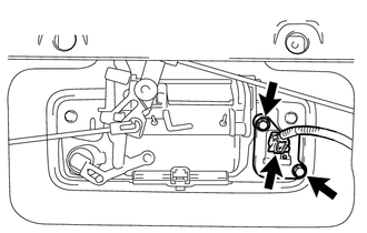
(b) Remove the 2 bolts and rear television camera assembly.
 Image from Camera for Rear View Monitor is Abnormal
DESCRIPTION
The display signal of the rear television camera assembly is transmitted to the
radio and display receiver assembly*1 or navigation receiver assembly*2.
*1: w/o Navigation Syste ...

Other materials:
Vehicle Speed Tolerance Malfunction (C1AA2)
DESCRIPTION
The forward recognition camera receives vehicle speed tolerance signals from
the combination meter assembly. If the combination meter assembly detects a vehicle
speed tolerance malfunction signal, it informs the forward recognition camera via
CAN communication, and DTC C1AA2 is st ...
Replacement
REPLACEMENT
PROCEDURE
1. REPLACE INTAKE VALVE GUIDE BUSH
(a) Heat the cylinder head to 80 to 100┬░C (176 to 212┬░F).
(b) Place the cylinder head on wooden blocks.
(c) Using SST and a hammer, tap out the intake valve guide bushes.
SST: 09201-10000
09201-01050
SST: 09950-70010 ...
Problem Symptoms Table
PROBLEM SYMPTOMS TABLE
HINT:
Use the table below to help determine the cause of problem symptoms.
If multiple suspected areas are listed, the potential causes of the symptoms
are listed in order of probability in the "Suspected Area" column of the
table. Check each sy ...
