Toyota Tacoma (2015-2018) Service Manual: System Diagram
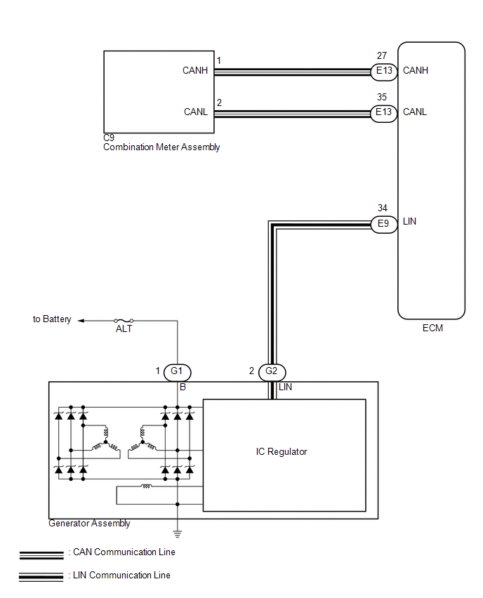
SYSTEM DIAGRAM
 Parts Location
PARTS LOCATION
ILLUSTRATION
...
 How To Proceed With Troubleshooting
CAUTION / NOTICE / HINT
HINT:
*: Use the Techstream.
PROCEDURE
1.
VEHICLE BROUGHT TO WORKSHOP
NEXT
...
Other materials:
Parts Location
PARTS LOCATION
ILLUSTRATION
ILLUSTRATION
ILLUSTRATION
ILLUSTRATION
...
Traction Off Switch
Components
COMPONENTS
ILLUSTRATION
Removal
REMOVAL
PROCEDURE
1. REMOVE ROOF CONSOLE BOX ASSEMBLY
(See page )
2. REMOVE A-TRAC SWITCH (TRACTION CONTROL SWITCH)
(a) Disconnect the A-TRAC switch (traction control switch) connector.
(b) Using a screwdriver, detach the 2 claws ...
Crankshaft Position Sensor "A" Signal Stuck in Range (P03352A,P033531)
DESCRIPTION
The crankshaft position sensor system consists of a crankshaft position sensor
plate and a pickup coil. The crankshaft position sensor plate has 34 teeth and is
installed to the crankshaft. The pickup coil is made of wound copper wire, an iron
core and a magnet. The crankshaft pos ...
