Toyota Tacoma (2015-2018) Service Manual: System Diagram
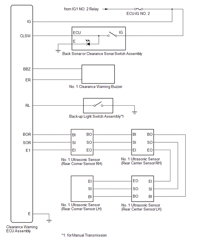
SYSTEM DIAGRAM
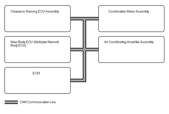 Communication Table
|
Sender |
Receiver |
Signal |
Line |
|---|---|---|---|
|
Main Body ECU (Multiplex Network Body ECU) |
Clearance Warning ECU Assembly |
Destination information signal |
CAN Communication Line |
|
ECM |
Clearance Warning ECU Assembly |
Shift position signal |
CAN Communication Line |
|
Combination Meter Assembly |
Clearance Warning ECU Assembly |
Vehicle speed signal |
CAN Communication Line |
|
Air Conditioning Amplifier Assembly |
Clearance Warning ECU Assembly |
Ambient temperature display signal |
CAN Communication Line |
|
Clearance Warning ECU Assembly |
Combination Meter Assembly |
|
CAN Communication Line |
 Parts Location
PARTS LOCATION
ILLUSTRATION
ILLUSTRATION
...
 How To Proceed With Troubleshooting
CAUTION / NOTICE / HINT
HINT:
Use the following procedure to troubleshoot the intuitive parking assist
system.
*: Use the Techstream.
PROCEDURE
1.
VEHI ...
Other materials:
System Description
SYSTEM DESCRIPTION
1. GENERAL
This system has the following functions: manual slide open and close; auto slide
open and close; manual tilt up and down; auto tilt up and down; jam protection;
key off operation; key-linked open and close; wireless transmitter-linked open sliding
roof open warn ...
On-vehicle Inspection
ON-VEHICLE INSPECTION
PROCEDURE
1. INSPECT COOLER CONDENSER ASSEMBLY
(a) If the fins of the cooler condenser assembly are dirty, clean them with water
and dry them with compressed air.
NOTICE:
Do not damage the fins of the condenser assembly.
(b) If the fins of the cooler condenser assembly ...
Clutch Switch Circuit
DESCRIPTION
Clutch switch circuit inspection is necessary for manual transmission vehicles.
When the clutch pedal is released, the ECM receives the positive (+) battery
voltage through the ECU-IG NO. 2 fuse and ignition switch. While the clutch pedal
is depressed, the clutch switch assembly se ...
