Toyota Tacoma (2015-2018) Service Manual: Parts Location
PARTS LOCATION
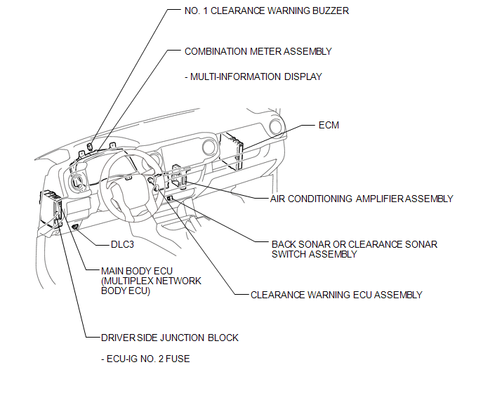
ILLUSTRATION
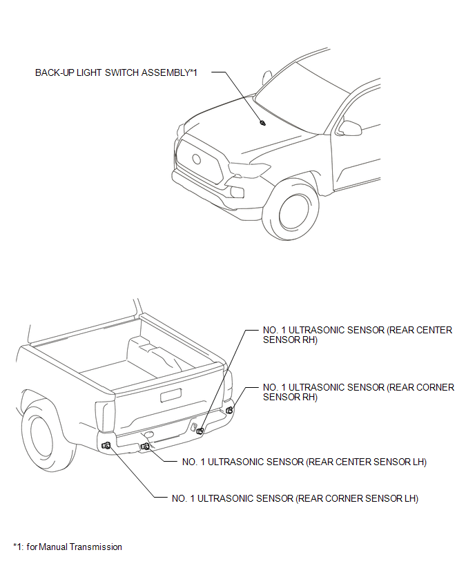
ILLUSTRATION
 Precaution
PRECAUTION
1. IGNITION SWITCH EXPRESSIONS
(a) The type of ignition switch used on this model differs according to the specifications
of the vehicle. The expressions listed in the table below are u ...
 System Diagram
SYSTEM DIAGRAM
Communication Table
Sender
Receiver
Signal
Line
Main Body ECU
(Multiplex Network Body ECU)
Clearance Warn ...
Other materials:
ECM Communication Circuit Malfunction (C1203)
DESCRIPTION
The circuit is used to send TRAC and VSC control information from the skid control
ECU (brake actuator assembly) to the ECM, and engine control information from the
ECM to the skid control ECU (brake actuator assembly) through the CAN communication
system.
for 4WD or w/ Rear Diff ...
On-vehicle Inspection
ON-VEHICLE INSPECTION
PROCEDURE
1. INSPECT RADIATOR CAP SUB-ASSEMBLY
CAUTION:
Do not remove the radiator cap sub-assembly while the engine and radiator assembly
are still hot. Pressurized, hot engine coolant and steam may be released and cause
serious burns.
(a) Measure the valve opening pr ...
Disassembly
DISASSEMBLY
PROCEDURE
1. REMOVE STEERING INTERMEDIATE SHAFT ASSEMBLY
(a) Put matchmarks on the steering intermediate shaft assembly and steering main
shaft assembly.
(b) Remove the bolt and steering intermediate shaft assembly.
2. REMOVE UPPER STEERING COLUMN BRACKET WITH SWITCH ASSEMBLY (w ...
