Toyota Tacoma (2015-2018) Service Manual: System Diagram
SYSTEM DIAGRAM
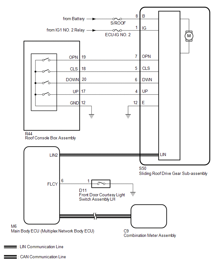
 System Description
SYSTEM DESCRIPTION
1. GENERAL
This system has the following functions: manual slide open and close; auto slide
open and close; manual tilt up and down; auto tilt up and down; jam protection;
key ...
 Customize Parameters
CUSTOMIZE PARAMETERS
PROCEDURE
1. CUSTOMIZE SLIDING ROOF SYSTEM
HINT:
The following items can be customized.
NOTICE:
When the customer requests a change in a function, first make sure th ...
Other materials:
Disposal
DISPOSAL
CAUTION / NOTICE / HINT
HINT:
The tire pressure warning valve and transmitter is powered by a lithium battery.
When disposing of the tire pressure warning valve and transmitter, remove the battery
and dispose of it correctly.
PROCEDURE
1. DISPOSE OF TIRE PRESSURE WARNING VALVE AND ...
Data List / Active Test
DATA LIST / ACTIVE TEST
1. DATA LIST
HINT:
Using the Techstream to read the Data List allows the values or states of switches,
sensors, actuators and other items to be read without removing any parts. This non-intrusive
inspection can be very useful because intermittent conditions or signals ...
TC and CG Terminal Circuit
DESCRIPTION
Tire pressure warning system DTCs can be checked by connecting terminals 13 (TC)
and 4 (CG) of the DLC3. The DTCs are indicated by blinking the tire pressure warning
light.
WIRING DIAGRAM
PROCEDURE
1.
CHECK CAN COMMUNICATION SYSTEM
(a) Check for ...
