Toyota Tacoma (2015-2018) Service Manual: System Diagram
SYSTEM DIAGRAM
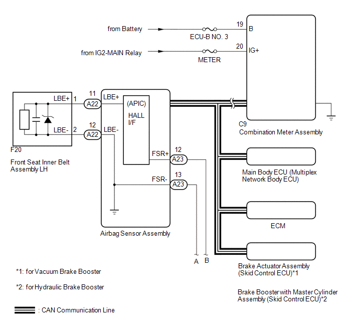
 Communication Table
|
Sender |
Receiver |
Signal |
Communication Method |
|---|---|---|---|
|
Airbag sensor assembly |
Main body ECU |
Front seat inner belt assembly LH buckle switch |
CAN |
|
Combination meter assembly |
|
||
|
Main body ECU |
Combination meter assembly |
Front seat inner belt assembly LH buckle switch |
|
|
Brake actuator assembly (Skid control ECU) |
Combination meter assembly |
Vehicle speed |
|
|
ECM |
Combination meter assembly |
Shift position |
 Precaution
PRECAUTION
1. IGNITION SWITCH EXPRESSIONS
(a) The type of ignition switch used on this model differs according to the specifications
of the vehicle. The expressions listed in the table below are u ...
 Customize Parameters
CUSTOMIZE PARAMETERS
1. CUSTOMIZE FUNCTION WITH TECHSTREAM
NOTICE:
Be sure to record the current settings before customizing.
These buzzers should be ON for safe driving. Perform these ...
Other materials:
Rear Power Outlet Switch
Components
COMPONENTS
ILLUSTRATION
Inspection
INSPECTION
PROCEDURE
1. INSPECT MAIN SWITCH ASSEMBLY
(a) Check the main switch assembly.
(1) Measure the resistance according to the value(s) in the table below.
Text in Illustration
*a
Com ...
Installation
INSTALLATION
CAUTION / NOTICE / HINT
HINT:
The following procedures are for BD22 (w/o Differential Lock).
PROCEDURE
1. INSTALL DIFFERENTIAL CARRIER ASSEMBLY REAR
(a) Clean the contact surfaces of the rear differential carrier assembly and
axle housing.
(b) Install the rear differential carr ...
Brake Warning Light does not Come ON
DESCRIPTION
Refer to Brake Warning Light Remains ON (See page
).
WIRING DIAGRAM
Refer to Brake Warning Light Remains ON (See page
).
CAUTION / NOTICE / HINT
NOTICE:
When replacing the skid control ECU (master cylinder solenoid), perform
calibration (See page
).
Inspect ...
