Toyota Tacoma (2015-2018) Service Manual: Short in Torque Converter Clutch Solenoid Circuit (Shift Solenoid Valve SL) (P2769,P2770)
DESCRIPTION
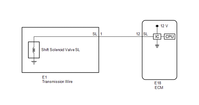
Shift solenoid valve SL is turned on and off by signals from the ECM to control the hydraulic pressure acting on the lock-up relay valve, which then controls operation of the lock-up clutch.
|
DTC No. |
DTC Detection Condition |
Trouble Area |
|---|---|---|
|
P2769 |
ECM detects a short in the shift solenoid valve SL circuit when the shift solenoid valve SL is operated (2 trip detection logic). |
|
|
P2770 |
ECM detects an open in the shift solenoid valve SL circuit when the shift solenoid valve SL is not operated (2 trip detection logic). |
|
Fail-safe function:
If the ECM detects a malfunction, it turns shift solenoid valve SL off.
MONITOR DESCRIPTION
Based on the signals from the throttle position sensor, the air flow meter and the crankshaft position sensor, the ECM sends a signal to shift solenoid valve SL to regulate the hydraulic pressure and provide smoother torque converter engagement. Shift solenoid valve SL responds to commands from the ECM. The valve controls the lock-up relay valve to perform the torque-converter lock-up function. If the ECM detects an open or short in the shift solenoid valve SL circuit, it will illuminate the MIL and store the DTC.
MONITOR STRATEGY
|
Related DTCs |
P2769: Shift solenoid valve SL/Range check P2770: Shift solenoid valve SL/Range check |
|
Required sensors/Components |
Shift solenoid valve SL |
|
Frequency of operation |
Continuous |
|
Duration |
1 time |
|
MIL operation |
2 driving cycles |
|
Sequence of operation |
None |
TYPICAL ENABLING CONDITIONS
All:|
The monitor will run whenever the following DTCs are not stored |
None |
|
Battery voltage |
8 V or higher |
|
Ignition switch |
ON |
|
Starter |
OFF |
|
Command to shift solenoid valve SL |
ON |
|
Time after command to solenoid OFF to ON |
0.008 sec. or more |
|
Time after command to solenoid ON to OFF |
0.008 sec. or more |
TYPICAL MALFUNCTION THRESHOLDS
P2769:|
Solenoid terminal voltage level |
Low |
|
Solenoid terminal voltage level |
High |
COMPONENT OPERATING RANGE
|
Solenoid terminal voltage level (Command to solenoid ON) |
High |
|
Solenoid terminal voltage level (Command to solenoid OFF) |
Low |
WIRING DIAGRAM
CAUTION / NOTICE / HINT
NOTICE:
- Perform the universal trip to clear permanent DTCs (See page
.gif) ).
). - Perform registration and/or initialization when parts related to the
automatic transmission are replaced (See page
).
HINT:
After the repair, clear the DTCs and perform the following procedure to check that DTCs are not output.
- Perform the Lock-up Function in Road Test (See page
).*1
- Turn the ignition switch off.
- Perform step (*1) again.
- Check for DTCs again (See page ).
PROCEDURE
|
1. |
INSPECT TRANSMISSION WIRE (SHIFT SOLENOID VALVE SL) |
|
(a) Disconnect the E1 transmission wire connector. |
|
(b) Measure the resistance according to the value(s) in the table below.
Standard Resistance:
|
Tester Connection |
Condition |
Specified Condition |
|---|---|---|
|
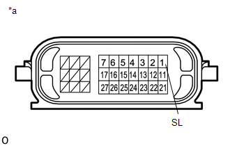
1 (SL) - Body ground |
20°C (68°F) |
11 to 15 Ω |
|
*a |
Component without harness connected (Transmission Wire) |
| NG | .gif) |
GO TO STEP 3 |
|
.gif)
|
2. |
CHECK HARNESS AND CONNECTOR (TRANSMISSION WIRE - ECM) |
|
(a) Disconnect the ECM connector. |
|
(b) Measure the resistance according to the value(s) in the table below.
Standard Resistance:
|
Tester Connection |
Condition |
Specified Condition |
|---|---|---|
|
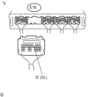
E18-12 (SL) - Body ground |
20°C (68°F) |
11 to 15 Ω |
|
*a |
Rear view of wire harness connector (to ECM) |
| OK | |
REPLACE ECM |
| NG | |
REPAIR OR REPLACE HARNESS OR CONNECTOR |
|
3. |
INSPECT SHIFT SOLENOID VALVE SL |
|
(a) Remove shift solenoid valve SL (See page
|
|
(b) Measure the resistance according to the value(s) in the table below.
Standard Resistance:
|
Tester Connection |
Condition |
Specified Condition |
|---|---|---|
|
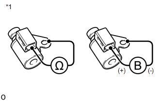
Shift solenoid valve SL connector terminal - Shift solenoid valve SL body |
20°C (68°F) |
11 to 15 Ω |
(c) Apply 12 V battery voltage to the shift solenoid valve and check that the valve moves and makes an operating noise.
OK:
|
Measurement Condition |
Specified Condition |
|---|---|
|
Valve moves and makes an operating noise |
|
*1 |
Shift Solenoid Valve SL |
| OK | |
REPLACE TRANSMISSION WIRE |
| NG | |
REPLACE SHIFT SOLENOID VALVE SL |
 Transmission Fluid Temperature Sensor "B" Circuit Low Input (P2742,P2743)
DESCRIPTION
The No. 2 ATF temperature sensor is installed in the transmission valve body
assembly.
If the ECM detects an abnormally high ATF temperature near this sensor, it illuminates
the warn ...
 Transmission Range Sensor Circuit Malfunction (PRNDL Input) (P0705)
DESCRIPTION
The park/neutral position switch detects the shift lever position and sends signals
to the ECM.
DTC No.
DTC Detection Condition
Trouble Area
...
Other materials:
On-vehicle Inspection
ON-VEHICLE INSPECTION
PROCEDURE
1. INSPECT ENGINE COOLANT
(See page )
2. INSPECT ENGINE OIL
(See page )
3. INSPECT BATTERY
(See page )
4. INSPECT SPARK PLUG
(See page )
5. INSPECT AIR CLEANER FILTER ELEMENT SUB-ASSEMBLY
(a) Remove the air cleaner filter element sub-assembly.
(b) Visu ...
System Description
SYSTEM DESCRIPTION
1. WIRELESS CHARGER FUNCTION OUTLINE
(a) The wireless charging system enables Qi-compliant* rechargeable devices,
such as a cellular phone, to be recharged by merely placing it on the charging area
of the mobile wireless charger cradle assembly on the console panel.
HINT:
...
Diagnostic Trouble Code Chart
DIAGNOSTIC TROUBLE CODE CHART
NOTICE:
When removing any parts, turn the ignition switch off.
HINT:
If no abnormality is found when inspecting parts, check the skid control
ECU and check for poor contact at ground points.
When 2 or more DTCs are detected, perform each circuit insp ...
