Toyota Tacoma (2015-2018) Service Manual: Satellite Radio Tuner
Components
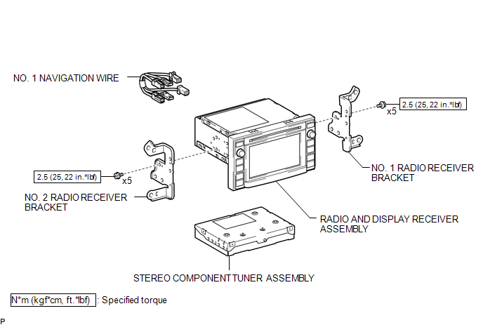
COMPONENTS
ILLUSTRATION
Removal
REMOVAL
PROCEDURE
1. REMOVE RADIO AND DISPLAY RECEIVER ASSEMBLY WITH BRACKET
(See page .gif) )
)
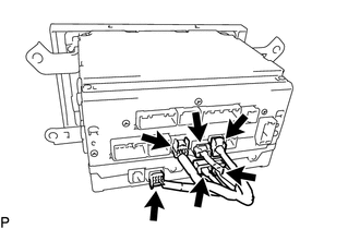
2. REMOVE NO. 1 NAVIGATION WIRE
|
(a) Disconnect the 6 connectors to remove the No. 1 navigation wire. |
|
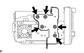
3. REMOVE NO. 1 RADIO RECEIVER BRACKET
|
(a) Remove the 5 bolts and No. 1 radio receiver bracket. |
|
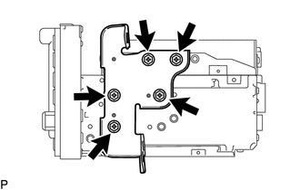
4. REMOVE NO. 2 RADIO RECEIVER BRACKET
|
(a) Remove the 5 bolts and No. 2 radio receiver bracket. |
|
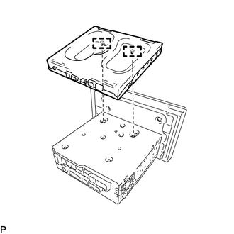
5. REMOVE STEREO COMPONENT TUNER ASSEMBLY
|
(a) Disengage the 2 guides to remove the stereo component tuner assembly as shown in the illustration. |
|
Installation
INSTALLATION
PROCEDURE
1. INSTALL STEREO COMPONENT TUNER ASSEMBLY
(a) Engage the 2 guides to install the stereo component tuner assembly.
2. INSTALL NO. 2 RADIO RECEIVER BRACKET
(a) Install the No. 2 radio receiver bracket with the 5 bolts.
Torque:
2.5 N·m {25 kgf·cm, 22 in·lbf}
3. INSTALL NO. 1 RADIO RECEIVER BRACKET
(a) Install the No. 1 radio receiver bracket with the 5 bolts.
Torque:
2.5 N·m {25 kgf·cm, 22 in·lbf}
4. INSTALL NO. 1 NAVIGATION WIRE
(a) Connect the 6 connectors to install the No. 1 navigation wire.
5. INSTALL RADIO AND DISPLAY RECEIVER ASSEMBLY WITH BRACKET
(See page .gif) )
)
 Installation
INSTALLATION
CAUTION / NOTICE / HINT
HINT:
Use the same procedure for the RH and LH sides.
The procedure listed below is for the LH side.
PROCEDURE
1. INSTALL REAR SPEAKER ASSEM ...
 Steering Pad Switch
Components
COMPONENTS
ILLUSTRATION
*1
STEERING PAD SWITCH ASSEMBLY
-
-
Removal
REMOVAL
PROCEDURE
1. REMOVE STEERING PAD
(See page )
...
Other materials:
Lost Communication with Alternator Missing Message (P161A87)
DESCRIPTION
The ECM communicates with the generator assembly via LIN communication. If a
LIN communication error is detected, the ECM stores this DTC.
DTC No.
DTC Detection Condition
Trouble Area
P161A87
Generator assembly or ECM commu ...
Inspection
INSPECTION
PROCEDURE
1. INSPECT NO. 1 ULTRASONIC SENSOR
(a) Measure the resistance according to the value(s) in the table below.
Text in Illustration
*a
Component without harness connected:
(No. 1 Ultrasonic Sensor)
Standar ...
Air Mix Damper Control Servo Motor Circuit (Driver Side) (B1446/46)
DESCRIPTION
This No. 3 air conditioning radiator damper servo sub-assembly (for driver side
air mix) is controlled by the air conditioning amplifier assembly and moves the
air mix damper (for driver side) to the desired position.
DTC No.
DTC Detection Condition
...
