REMOVAL
CAUTION / NOTICE / HINT
HINT:
PROCEDURE
1. REMOVE FRONT NO. 1 WHEEL OPENING EXTENSION PAD
Click here
2. SEPARATE FRONT FENDER LINER
|
(a) Remove the 2 screws to separate the front fender liner. |
|
3. REMOVE FOG LIGHT ASSEMBLY
|
(a) Disconnect the connector. |
|
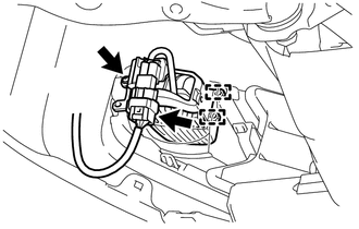
(b) Remove the screw.
(c) Disengage the 2 guides to remove the fog light assembly.
Adjustment
InstallationSound Signal Circuit between Radio Receiver and Stereo Component Amplifier
DESCRIPTION
The navigation receiver assembly sends a sound signal to the stereo component
amplifier assembly via this circuit.
The sound signal that has been sent is amplified by the stereo component amplifier
assembly, and then is sent to the speakers.
If there is an open or short in the cir ...
System Description
SYSTEM DESCRIPTION
1. POWER DOOR LOCK CONTROL SYSTEM DESCRIPTION
(a) The power door lock system locks/unlocks all the doors.
The main body ECU (multiplex network body ECU) receives lock/unlock request signals
from a door control switch or the driver door key lock and unlock switch. Then,
the ...
Speed Sensor
Components
COMPONENTS
ILLUSTRATION
Removal
REMOVAL
PROCEDURE
1. REMOVE TRANSMISSION REVOLUTION SENSOR (NT)
(a) Disconnect the transmission revolution sensor (NT) connector.
(b) Remove the bolt and transmission revolution sensor (NT). ...