DESCRIPTION
The distance control switch is used to set the distance for vehicle-to-vehicle distance control mode. The distance control switch is installed in the steering pad switch assembly. The vehicle-to-vehicle distance set value can be changed by operating the steering pad switch assembly (distance control switch) while the dynamic radar cruise control system is controlling vehicle speed in vehicle-to-vehicle distance control mode.
WIRING DIAGRAM
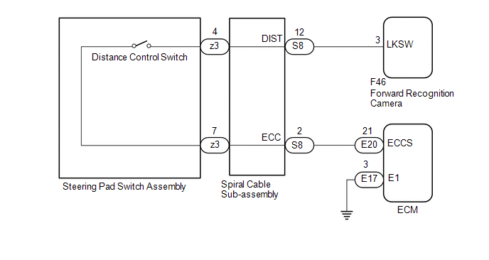
CAUTION / NOTICE / HINT
NOTICE:
- Before replacing the ECM, refer to Registration.
w/o Smart Key System: Click here
.gif)
w/ Smart Key System: Click here
- The vehicle is equipped with a Supplemental Restraint System (SRS) which
includes components such as airbags. Before servicing (including removal
or installation of parts), be sure to read the precaution for Supplemental
Restraint System.
Click here
- When replacing the forward recognition camera, always replace it with a new one. If a forward recognition camera which was installed to another vehicle is used, the information stored in the forward recognition camera will not match the information from the vehicle. As a result, a DTC may be stored.
- If the forward recognition camera has been replaced with a new one,
be sure to perform Forward Recognition Camera Learning.
Click here
PROCEDURE
|
1. |
READ VALUE ON TECHSTREAM (DISTANCE CONTROL SWITCH) |
(a) Connect the Techstream to the DLC3.
(b) Turn the ignition switch to ON.
(c) Turn the Techstream on.
(d) Enter the following menus: Powertrain / Radar Cruise 2 / Data List.
(e) Read the Data List according to the display on the Techstream.
Powertrain > Radar Cruise2 > Data List
|
Tester Display |
Measurement Item |
Range |
Normal Condition |
Diagnostic Note |
|---|---|---|---|---|
|
Distance Control Switch |
Distance control switch signal |
ON or OFF |
ON: Distance control switch on OFF: Distance control switch off |
- |
OK:
The Data List item shown in the table changes according to the operation of the steering pad switch assembly (distance control switch).
| OK | .gif) |
PROCEED TO NEXT SUSPECTED AREA SHOWN IN PROBLEM SYMPTOMS TABLE |
|
.gif)
|
2. |
INSPECT STEERING PAD SWITCH ASSEMBLY |
(a) Remove the steering pad switch assembly.
Click here
(b) Inspect the steering pad switch assembly.
Click here
| NG | |
REPLACE STEERING PAD SWITCH ASSEMBLY |
|
|
3. |
INSPECT SPIRAL CABLE WITH SENSOR SUB-ASSEMBLY |
(a) Remove the spiral cable with sensor sub-assembly.
Click here
(b) Inspect the spiral cable with sensor sub-assembly.
Click here
| NG | |
REPLACE SPIRAL CABLE WITH SENSOR SUB-ASSEMBLY |
|
|
4. |
CHECK HARNESS AND CONNECTOR (SPIRAL CABLE WITH SENSOR SUB-ASSEMBLY - FORWARD RECOGNITION CAMERA, ECM AND BODY GROUND) |
(a) Disconnect the S8 spiral cable with sensor sub-assembly connector.
(b) Disconnect the F46 forward recognition camera connector.
(c) Disconnect the E20 ECM connector.
(d) Measure the resistance according to the value(s) in the table below.
Standard Resistance:
|
Tester Connection |
Condition |
Specified Condition |
|---|---|---|
|
S8-12 (DIST) - F46-3 (LKSW) |
Always |
Below 1 Ω |
|
S8-2 (ECC) - E20-21 (ECCS) |
Always |
Below 1 Ω |
|
S8-12 (DIST) or F46-3 (LKSW) - Body ground |
Always |
10 kΩ or higher |
|
S8-2 (ECC) or E20-21 (ECCS) - Body ground |
Always |
10 kΩ or higher |
| NG | |
REPAIR OR REPLACE HARNESS OR CONNECTOR |
|
|
5. |
CHECK HARNESS AND CONNECTOR (ECM - BODY GROUND) |
(a) Disconnect the E20 ECM connector.
(b) Measure the resistance according to the value(s) in the table below.
Standard Resistance:
|
Tester Connection |
Condition |
Specified Condition |
|---|---|---|
|
S8-2 (ECC) or E20-21 (E1) -Body ground |
Always |
Below 1 Ω |
| NG | |
REPAIR OR REPLACE HARNESS OR CONNECTOR |
|
|
6. |
CHECK ECM (ECM TERMINALS) |
(a) Disconnect the E20 and E17 ECM connectors.
(b) Measure the resistance according to the value(s) in the table below.
Standard Resistance:
|
Tester Connection |
Condition |
Specified Condition |
|---|---|---|
|
E20-21 (ECCS) - E17-3 (E1) |
Always |
Below 1 Ω |
| OK | |
REPLACE FORWARD RECOGNITION CAMERA |
| NG | |
REPLACE ECM |