Toyota Tacoma (2015-2018) Service Manual: Installation
INSTALLATION
PROCEDURE
1. INSTALL TRANSMISSION CASE GASKET
(a) Install 2 new transmission case gaskets to the automatic transmission case sub-assembly.
2. INSTALL MANUAL VALVE
(a) Coat the manual valve with ATF and install it to the transmission valve body assembly.
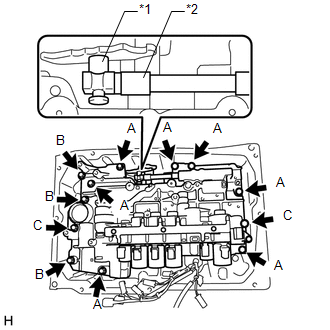
3. INSTALL TRANSMISSION VALVE BODY ASSEMBLY
|
(a) Insert the manual valve lever sub-assembly into the groove on the end of the manual valve and install the transmission valve body assembly to the automatic transmission case sub-assembly with the 12 bolts. Text in Illustration
Torque: 11 N·m {112 kgf·cm, 8 ft·lbf} HINT: Bolt length:
|
|
(b) Install the detent spring and detent spring cover to the transmission valve body assembly with the bolt.
Torque:
10 N·m {102 kgf·cm, 7 ft·lbf}
4. INSTALL VALVE BODY OIL STRAINER ASSEMBLY
(a) Coat a new O-ring with ATF, and install it to the valve body oil strainer assembly.
(b) Install the valve body oil strainer assembly to the transmission valve body assembly with the 3 bolts.
Torque:
10 N·m {102 kgf·cm, 7 ft·lbf}
5. CONNECT TRANSMISSION WIRE
(See page .gif) )
)
6. CHECK AUTOMATIC TRANSMISSION SYSTEM
(See page )
 Reassembly
REASSEMBLY
PROCEDURE
1. INSTALL SHIFT SOLENOID VALVE SLT
(a) Install the shift solenoid valve SLT and straight pin to the transmission
valve body assembly.
...
 Axle
Axle
...
Other materials:
Power Source Circuit
DESCRIPTION
This circuit provides power to operate the forward recognition camera.
WIRING DIAGRAM
CAUTION / NOTICE / HINT
NOTICE:
Inspect the fuses for circuits related to this system before performing the following
inspection procedure.
PROCEDURE
1.
CHECK HARNESS A ...
Main Switch Power Source Circuit
DESCRIPTION
This circuit supplies power to the wireless charger main switch (mobile wireless
charger switch) and illuminates the switch indicator light when the wireless charger
main switch (mobile wireless charger switch) is turned on.
WIRING DIAGRAM
CAUTION / NOTICE / HINT
NOTICE:
Inspe ...
Auto Down Operation does not Fully Open Power Window (Catch Protection Function
is Activated)
DESCRIPTION
If a front door glass or the power window regulator motor assembly (for driver
door) or power window regulator motor assembly (front passenger door) does not operate
smoothly, the catch protection function may be triggered automatically, resulting
in the auto down operation being ...
