Components
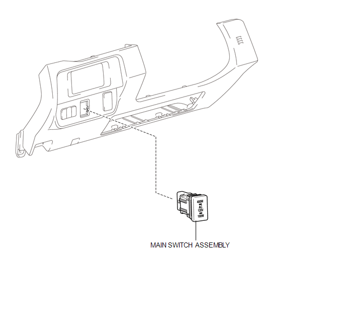
COMPONENTS
ILLUSTRATION
Inspection
INSPECTION
PROCEDURE
1. INSPECT MAIN SWITCH ASSEMBLY
(a) Check the main switch assembly.
|
(1) Measure the resistance according to the value(s) in the table below. Text in Illustration
Standard Resistance:
|
|
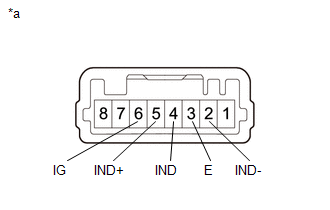
(b) Check the switch indicator.
(1) Apply battery voltage to the main switch assembly and check that the switch indicator illuminates.
OK:
|
Measurement Condition |
Switch Condition |
Specified Condition |
|---|---|---|
|
Battery positive (+) → 5 (IND+) Battery positive (-) → 2 (IND-) |
Always |
Illuminates |
OK:
|
Measurement Condition |
Switch Condition |
Specified Condition |
|---|---|---|
|
Battery positive (+) → 6 (IG) Battery positive (-) → 4 (IND) |
Always |
Illuminates |
- If the specified condition is not met, replace the main switch assembly.
Removal
REMOVAL
PROCEDURE
1. REMOVE INSTRUMENT PANEL LOWER FINISH PANEL SUB-ASSEMBLY RH
(See page .gif) )
)
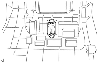
2. REMOVE MAIN SWITCH ASSEMBLY
|
(a) Disengage the 2 claws to remove the main switch assembly. |
|
Installation
INSTALLATION
PROCEDURE
1. INSTALL MAIN SWITCH ASSEMBLY
(a) Engage the 2 claws to install the main switch assembly.
2. INSTALL INSTRUMENT PANEL LOWER FINISH PANEL SUB-ASSEMBLY RH
(See page .gif) )
)