Components
COMPONENTS
ILLUSTRATION
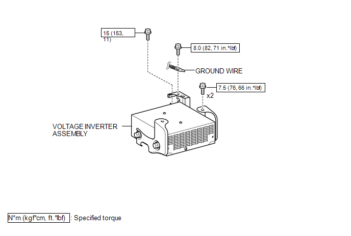
Inspection
INSPECTION
PROCEDURE
1. INSPECT VOLTAGE INVERTER ASSEMBLY
(a) Check the voltage inverter assembly.
(1) Measure the voltage according to the value(s) in the table below.
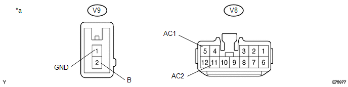 Text in Illustration
|
*a |
Component with harness connected (Voltage Inverter Assembly) |
- |
- |
Standard:
|
Tester Connection |
Switch Condition |
Specified Condition |
|---|---|---|
|
V9-2 (B) - V9-1 (GND) |
Ignition switch (ON) |
11 to 15 V |
|
V9-1 (GND) - Body ground |
Always |
Below 1 V |
|
V8-5 (AC1) - V8-11 (AC2) |
Ignition switch (ON) Main switch (ON) |
108 to 132 V |
If the result is not as specified, replace the voltage inverter assembly.
Removal
REMOVAL
PROCEDURE
1. REMOVE REAR CONSOLE BOX ASSEMBLY
(See page .gif) )
)
2. REMOVE VOLTAGE INVERTER ASSEMBLY
|
(a) Remove the bolt to disconnect the ground wire. |
|
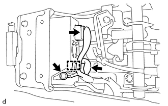
(b) Disconnect the 2 connectors and disengage the clamp.
|
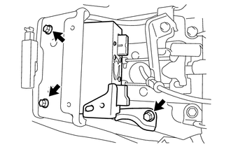
(c) Remove the 3 bolts and voltage inverter assembly. |
|
Installation
INSTALLATION
PROCEDURE
1. INSTALL VOLTAGE INVERTER ASSEMBLY
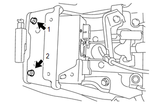
(a) Temporarily install the voltage inverter assembly with the 3 bolts.
|
(b) Tighten the 2 bolts in the order shown in the illustration. Torque: 7.5 N·m {76 kgf·cm, 66 in·lbf} |
|
|
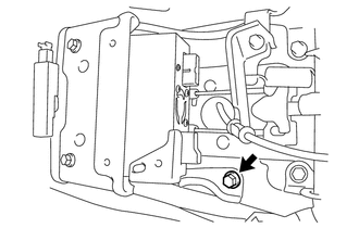
(c) Tighten the bolt. Torque: 15 N·m {153 kgf·cm, 11 ft·lbf} |
|
(d) Connect the 2 connectors and engage the clamp.
(e) Connect the ground wire with the bolt.
Torque:
8.0 N·m {82 kgf·cm, 71 in·lbf}
2. INSTALL REAR CONSOLE BOX ASSEMBLY
(See page .gif) )
)