Components
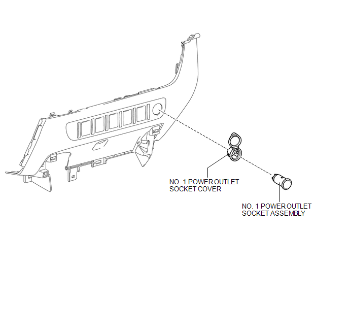
COMPONENTS
ILLUSTRATION
Removal
REMOVAL
PROCEDURE
1. REMOVE INSTRUMENT PANEL LOWER CENTER FINISH PANEL
(See page .gif) )
)
2. REMOVE NO. 1 POWER OUTLET SOCKET ASSEMBLY
|
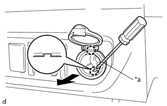
(a) Using a screwdriver with its tip wrapped in protective tape, disengage the 2 claws to remove the No. 1 power outlet socket assembly as shown in the illustration. Text in Illustration
|
|
3. REMOVE NO. 1 POWER OUTLET SOCKET COVER
|
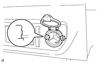
(a) Disengage the 2 claws to remove the No. 1 power outlet socket cover. |
|
Installation
INSTALLATION
PROCEDURE
1. INSTALL NO. 1 POWER OUTLET SOCKET COVER
(a) Engage the 2 claws to install the No. 1 power outlet socket cover.
2. INSTALL NO. 1 POWER OUTLET SOCKET ASSEMBLY
|
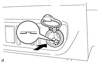
(a) Engage the 2 claws to install the No. 1 power outlet socket assembly as shown in the illustration. |
|
3. INSTALL INSTRUMENT PANEL LOWER CENTER FINISH PANEL
(See page .gif) )
)