Toyota Tacoma (2015-2018) Service Manual: Components
COMPONENTS
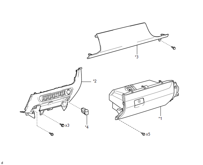
ILLUSTRATION
|
*1 |
INSTRUMENT LOWER PANEL ASSEMBLY |
*2 |
INSTRUMENT PANEL LOWER CENTER FINISH PANEL |
|
*3 |
NO. 2 INSTRUMENT PANEL GARNISH SUB-ASSEMBLY |
*4 |
REAR NO. 2 POWER WINDOW REGULATOR SWITCH ASSEMBLY |

 Inspection
INSPECTION
PROCEDURE
1. INSPECT REAR NO. 2 POWER WINDOW REGULATOR SWITCH ASSEMBLY
*a
Component without harness connected
(Rear No. 2 Power Window Regulator Switch Assembl ...
Other materials:
Open in One Side of Bus 5 Branch Line
DESCRIPTION
When the CAN bus main lines are normal (no open, short to ground, short to +B
or short between lines) and there is an ECU or sensor on the "Communication Bus
Check" screen that is indicated as not communicating or whose connection status
on the "Communication Bus Ch ...
Theft Deterrent System Unexpectedly Sets Itself
DESCRIPTION
A situation in which the theft deterrent system unexpectedly sets itself can
be caused when the main body ECU (multiplex network body ECU) cannot detect whether
a door is open or closed.
If the theft deterrent system unexpectedly sets itself, there may be a malfunction
in a court ...
Problem Symptoms Table
PROBLEM SYMPTOMS TABLE
HINT:
Use the table below to help determine the cause of problem symptoms.
If multiple suspected areas are listed, the potential causes of the symptoms
are listed in order of probability in the "Suspected Area" column of the
table. Check each sy ...
