Toyota Tacoma (2015-2018) Service Manual: Parts Location
PARTS LOCATION
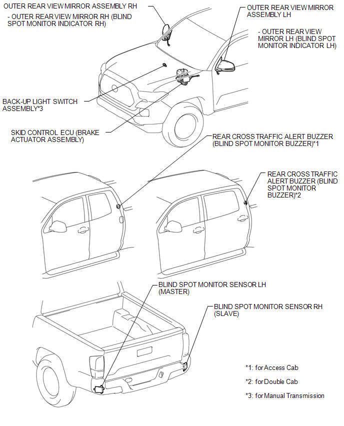
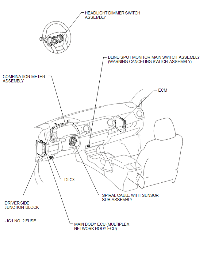
ILLUSTRATION
ILLUSTRATION
 Precaution
PRECAUTION
1. IGNITION SWITCH EXPRESSIONS
(a) The type of ignition switch used on this model differs according to the specifications
of the vehicle. The expressions listed in the table below are u ...
 System Description
SYSTEM DESCRIPTION
1. GENERAL
(a) The blind spot monitor system has the blind spot monitor function and rear
cross traffic alert function.
(1) Blind spot monitor function
The blind spot m ...
Other materials:
Air Inlet Control Servo Motor
Inspection
INSPECTION
PROCEDURE
1. INSPECT AIR INLET CONTROL SERVO MOTOR
(a) Inspect the servo motor operation.
(1) Connect the positive (+) lead from the battery to terminal 1 (FRS)
and negative (-) lead to terminals 2 (REC), then check that the shaft rotates
clockwise s ...
Adjustment
ADJUSTMENT
PROCEDURE
1. BEFORE FILLING TRANSMISSION
The AC60E automatic transmission assembly requires Toyota Genuine ATF
WS.
If the entire automatic transmission assembly, automatic transmission
oil pan sub-assembly, drain plug, transmission valve body assembly and/or
torq ...
Installation
INSTALLATION
PROCEDURE
1. INSTALL OIL COOLER TUBE
(a) Install the oil cooler tube to the vehicle body with the 2 bolts.
Torque:
28 N·m {286 kgf·cm, 21 ft·lbf}
2. INSTALL NO. 4 OIL COOLER INLET HOSE AND NO. 4 OIL COOLER OUTLET HOSE
NOTICE:
When connecting the hoses to the tube, su ...
