Toyota Tacoma (2015-2018) Service Manual: Parts Location
PARTS LOCATION
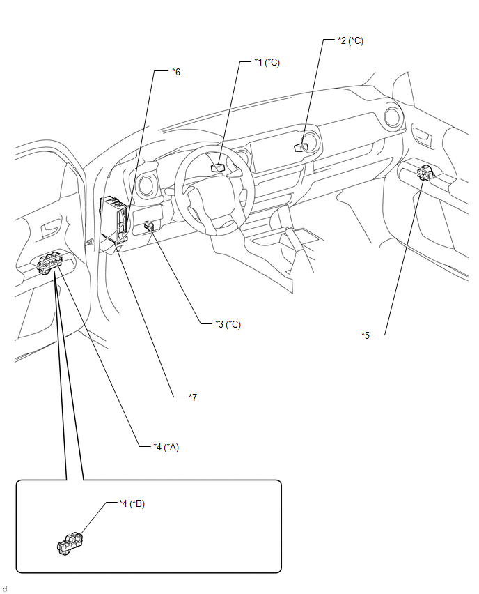
ILLUSTRATION
|
*A |
for Double Cab |
*B |
for Access Cab |
|
*C |
w/ Back Door Power Window |
- |
- |
|
*1 |
NO. 1 BACK PANEL RELAY |
*2 |
NO. 2 BACK PANEL RELAY |
|
*3 |
REAR NO. 2 POWER WINDOW REGULATOR SWITCH ASSEMBLY |
*4 |
POWER WINDOW REGULATOR MASTER SWITCH ASSEMBLY |
|
*5 |
FRONT POWER WINDOW REGULATOR SWITCH ASSEMBLY RH |
*6 |
MAIN BODY ECU(MULTIPLEX NETWORK BODY ECU) |
|
*7 |
DRIVER SIDE JUNCTION BLOCK - PWR RELAY - DOOR F/R FUSE - DOOR F/L FUSE - POWER NO. 1 FUSE - POWER NO. 2 FUSE |
- |
- |
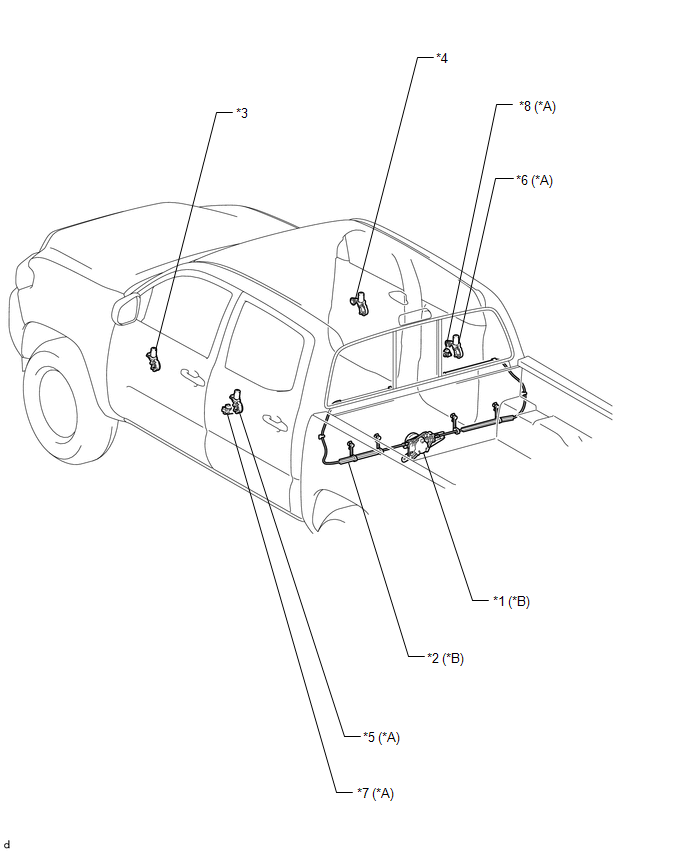
ILLUSTRATION
|
*A |
for Double Cab |
*B |
w/ Back Door Power Window |
|
*1 |
POWER WINDOW REGULATOR MOTOR ASSEMBLY |
*2 |
DOOR WINDOW REGULATOR CABLE SUB-ASSEMBLY |
|
*3 |
FRONT POWER WINDOW REGULATOR MOTOR ASSEMBLY LH |
*4 |
FRONT POWER WINDOW REGULATOR MOTOR ASSEMBLY RH |
|
*5 |
REAR POWER WINDOW REGULATOR MOTOR ASSEMBLY LH |
*6 |
REAR POWER WINDOW REGULATOR MOTOR ASSEMBLY RH |
|
*7 |
REAR POWER WINDOW REGULATOR SWITCH ASSEMBLY LH |
*8 |
REAR POWER WINDOW REGULATOR SWITCH ASSEMBLY RH |

 How To Proceed With Troubleshooting
CAUTION / NOTICE / HINT
HINT:
Use these procedures to troubleshoot the power window control system.
PROCEDURE
1.
VEHICLE BROUGHT TO WORK SHOP
...
Other materials:
Voice Guidance does not Function
PROCEDURE
1.
CHECK VOICE GUIDANCE SETTING
(a) Check that the voice guidance setting is not off.
OK:
Voice guidance setting is not off.
NG
CHANGE THE VOICE GUIDANCE SETTING TO ON
OK
...
Four Wheel Drive (4WD) Range Signal Circuit Range / Performance (P279E)
DESCRIPTION
When the transfer position switch is switched, the 2-4 terminal and LO terminal
change to one of the following ON/OFF combinations listed in the table below.
Terminal
2WD
Between 2WD and H4
H4
Between H4 and L4
L4
...
Correct driving posture
Drive in a good posture as follows:
Sit upright and well back in the
seat.
Adjust the position of the seat
forward or backward to ensure the pedals can be reached and easily depressed to
the extent required.
Adjust the seatback so that the
controls are easily operable.
Adjust the t ...
