Toyota Tacoma (2015-2018) Service Manual: Open in Pump Motor Circuit (C1251)
DESCRIPTION
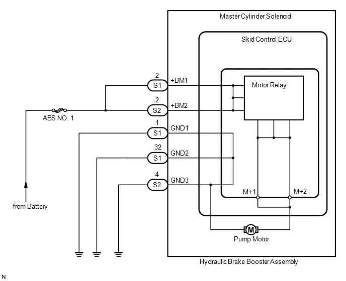
The motor relay (semiconductor relay) is built into the master cylinder solenoid and drives the pump motor based on a signal from the skid control ECU (master cylinder solenoid).
|
DTC No. |
DTC Detecting Condition |
Trouble Areas |
|---|---|---|
|
C1251 |
Open in motor system circuit (motor input circuit) |
Hydraulic brake booster pump motor circuit |
WIRING DIAGRAM
CAUTION / NOTICE / HINT
HINT:
Remove the hydraulic brake booster before the inspection (See page
.gif) ).
).
PROCEDURE
|
1. |
CHECK BRAKE PUMP MOTOR WIRE HARNESS CONNECTION (MT+ / MT-) |
(a) Using a screwdriver, remove the 2 plugs from the hydraulic brake booster
(See page ).
(b) Check the tightening torque of 2 screws which fasten the wire harness connecting
hydraulic brake booster and brake booster pump (See page
).
Torque:
2.9 N·m {30 kgf·cm, 26 in·lbf}
| NG | .gif) |
RETIGHTEN SCREWS |
|
.gif)
|
2. |
CHECK RESISTANCE OF PUMP MOTOR WIRE HARNESS (MT+/MT-) |
|
(a) Using a screwdriver, remove the 2 screws and pull the wire harness from the hydraulic brake booster. |
|
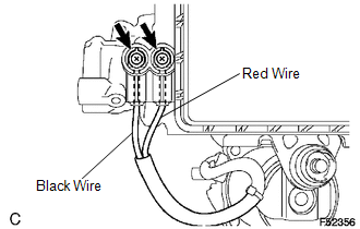
(b) Measure the resistance between the red wire (MT+) and black wire (MT-).
Resistance:
2 Ω
| NG | |
REPLACE HYDRAULIC BRAKE BOOSTER |
|
|
3. |
RECONFIRM DTC |
(a) Reassemble the hydraulic brake booster, then reinstall the hydraulic brake booster.
(b) Clear the DTCs (See page
).
(c) Check if the same DTCs are detected.
|
Result |
Proceed to |
|---|---|
|
DTC output |
A |
|
DTC not output |
B |
| A | |
REPLACE MASTER CYLINDER SOLENOID |
| B | |
END |
 Open Circuit in IG1/IG2 Power Source Circuit (C1242)
DESCRIPTION
If there is a problem with the skid control ECU (master cylinder solenoid) power
supply circuit, the skid control ECU outputs the DTC and prohibits operation under
the fail safe funct ...
 Brake Booster Pump Motor on Time Abnormally Long (C1252)
DESCRIPTION
The motor relay (semiconductor relay) is built into the master cylinder solenoid
and drives the pump motor based on a signal from the skid control ECU (master cylinder
solenoid).
...
Other materials:
Removal
REMOVAL
CAUTION / NOTICE / HINT
HINT:
Use the same procedure for both the RH and LH sides.
The procedure described below is for the LH side.
PROCEDURE
1. PRECAUTION
CAUTION:
Be sure to read Precaution thoroughly before servicing (See page
).
NOTICE:
After turning the ign ...
Parking Brake System
Adjustment
ADJUSTMENT
PROCEDURE
1. INSPECT PARKING BRAKE LEVER TRAVEL
(a) Fully pull the parking brake lever to engage the parking brake.
(b) Release the lever to disengage the parking brake.
(c) Slowly pull the parking brake lever all the way and count the number of clicks.
Standard parkin ...
Removal
REMOVAL
CAUTION / NOTICE / HINT
HINT:
Use the same procedures for the RH side and LH side.
The procedures listed below are for the LH side.
When removing the moulding, heat the vehicle body and moulding using
a heat light.
Heating Temperature
Item
...
