DESCRIPTION
The ABS solenoid relay is built into the master cylinder solenoid.
This relay supplies power to each ABS solenoid. After the ignition switch is turned ON, if the initial check is OK, the relay turns on.
|
DTC No. |
DTC Detecting Conditions |
Trouble Areas |
|---|---|---|
|
C146E |
When either of following condition detected:
|
|
|
C146F |
The following condition continues for at least 0.2 seconds.
|
|
WIRING DIAGRAM
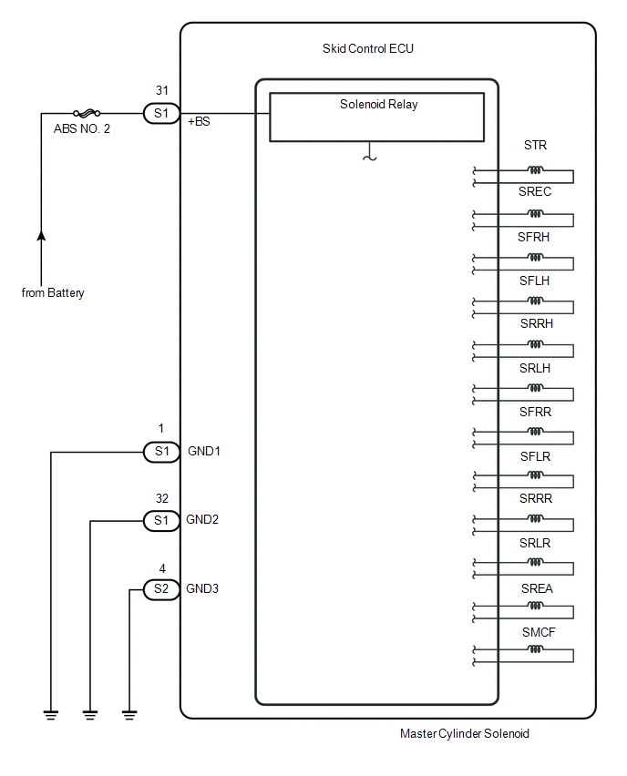
CAUTION / NOTICE / HINT
NOTICE:
- When replacing the skid control ECU (master cylinder solenoid), perform
zero point calibration (See page
.gif) ).
). - Inspect the fuses for circuits related to this system before performing the following inspection procedure.
PROCEDURE
|
1. |
INSPECT SKID CONTROL ECU CONNECTOR (+BS TERMINAL VOLTAGE) |
|
(a) Disconnect the skid control ECU connector. |
|
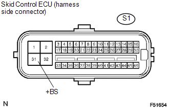
(b) Measure the voltage.
Standard Voltage:
|
Tester Connection |
Specified Condition |
|---|---|
|
S1-31 (+BS) - Body ground |
10 to 14 V |
(c) Reconnect the skid control ECU connector.
| NG | .gif) |
REPAIR OR REPLACE HARNESS OR CONNECTOR |
|
.gif)
|
2. |
CHECK HARNESS OR CONNECTOR (GND - BODY GROUND) |
|
(a) Disconnect the skid control ECU connectors. |
|
.png)
(b) Measure the resistance.
Standard Resistance:
|
Tester Connection |
Specified Condition |
|---|---|
|
S1-1, 32 (GND1, GND2) - Body ground |
Below 1 Ω |
|
S2-4 (GND3) - Body ground |
Below 1 Ω |
(c) Reconnect the skid control ECU connectors.
| NG | |
REPAIR OR REPLACE HARNESS OR CONNECTOR (GND CIRCUIT) |
|
|
3. |
RECONFIRM DTC |
(a) Clear the DTCs (See page
).
(b) Check if the same DTCs are recorded.
|
Result |
Proceed to |
|---|---|
|
DTC output |
A |
|
DTC not output |
B |
| A | |
REPLACE MASTER CYLINDER SOLENOID |
| B | |
END |