Toyota Tacoma (2015-2018) Service Manual: On-vehicle Inspection
ON-VEHICLE INSPECTION
PROCEDURE
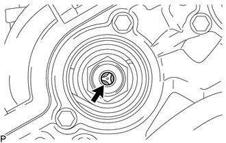
1. INSPECT CAMSHAFT TIMING GEAR BOLT
(a) Remove the camshaft timing oil control solenoid assembly (See page
.gif) ).
).
|
(b) Check that the plunger strokes when the plunger in the center of the camshaft timing gear bolt is pressed. Standard stroke: 4.5 mm (0.177 in.) or more HINT: When pressing the plunger, there is a stepped feeling but this is not a malfunction. If the result is not as specified, replace the camshaft timing gear bolt. |
|
(c) Install the camshaft timing oil control solenoid assembly (See page
).
 Components
COMPONENTS
ILLUSTRATION
...
 Removal
REMOVAL
CAUTION / NOTICE / HINT
NOTICE:
If one of the camshaft timing gear bolts is already removed, do not remove any
other camshaft timing gear bolts.
PROCEDURE
1. REMOVE NO. 2 ENGINE UNDER C ...
Other materials:
Disposal
DISPOSAL
PROCEDURE
1. DISPOSE OF FRONT SHOCK ABSORBER ASSEMBLY
(a) Fully extend the shock absorber piston rod, and fix it at an angle in a vise
or similar tool.
(b) Using a drill or similar tool, slowly make a hole in the shaded area shown
in the illustration, and discharge the gas inside. ...
Dtc Check / Clear
DTC CHECK / CLEAR
CHECK DTC
(a) Connect the Techstream to the DLC3.
(b) Turn the ignition switch to ON.
(c) Turn the Techstream on.
(d) Enter the following menus: Powertrain / Radar Cruise 1*1 / Trouble Codes.
(e) Enter the following menus: Powertrain / Radar Cruise 2*2 / Trouble Codes.
(f) C ...
Pressure Control Solenoid "A" Performance (Shift Solenoid Valve SL1) (P0746)
SYSTEM DESCRIPTION
The ECM uses the vehicle speed signal and signals from the transmission revolution
sensors (NT, SP2) to detect the actual gear (1st, 2nd, 3rd, 4th, 5th or 6th gear).
The ECM compares the actual gear with the shift schedule in the ECM memory to
detect mechanical problems of t ...
