Toyota Tacoma (2015-2018) Service Manual: On-vehicle Inspection
ON-VEHICLE INSPECTION
PROCEDURE
1. INSPECT AIR CONDITIONER PRESSURE SENSOR (for Automatic Air Conditioning System)
(a) Check the wire harness.
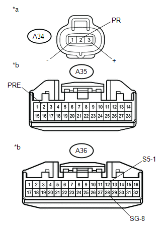
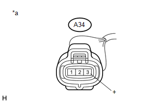
(1) Disconnect the A34 air conditioner pressure sensor connector.
(2) Disconnect the A35 and A36 air conditioning amplifier assembly connector.
|
(3) Measure the resistance according to the value(s) in the table below. Text in Illustration
Standard Resistance:
If the resistance is not as specified, repair the wire harness. |
|
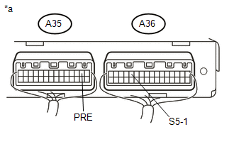
(4) Connect the A35 and A36 air conditioning amplifier assembly connector.
|
(5) Measure the voltage according to the value(s) in the table below. Text in Illustration
Standard Voltage:
If the voltage is not as specified, repair the wire harness or replace the air conditioning amplifier assembly. |
|
(b) Check the air conditioner pressure sensor.
(1) Install a manifold gauge set.
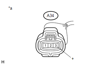
(2) Connect the A34 air conditioner pressure sensor connector.
(3) Warm up the engine.
(4) A/C switch on.
|
(5) Measure the voltage according to the value(s) in the table below. Text in Illustration
Standard Voltage:
If the voltage is not as specified, replace the air conditioner pressure sensor. |
|
2. INSPECT AIR CONDITIONER PRESSURE SENSOR (for Manual Air Conditioning System)
(a) Check the wire harness.
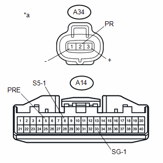
(1) Disconnect the A34 air conditioner pressure sensor connector.
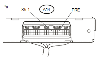
(2) Disconnect the A14 air conditioning amplifier assembly connector.
|
(3) Measure the resistance according to the value(s) in the table below. Text in Illustration
Standard Resistance:
If the resistance is not as specified, repair the wire harness. |
|
(4) Connect the A14 air conditioning amplifier assembly connector.
|
(5) Measure the voltage according to the value(s) in the table below. Text in Illustration
Standard Voltage:
If the voltage is not as specified, repair the wire harness or replace the air conditioning amplifier assembly. |
|
(b) Check the air conditioner pressure sensor.
(1) Install a manifold gauge set.
(2) Connect the A34 air conditioner pressure sensor connector.
(3) Warm up the engine.
(4) A/C switch on.
|
(5) Measure the voltage according to the value(s) in the table below. Text in Illustration
Standard Voltage:
If the voltage is not as specified, replace the air conditioner pressure sensor. |
|
 Installation
INSTALLATION
PROCEDURE
1. INSTALL AIR CONDITIONER PRESSURE SENSOR
(a) Remove the vinyl tape from the air conditioner tube and accessory assembly
and connecting part of the air conditioner pressur ...
 Removal
REMOVAL
PROCEDURE
1. REMOVE REFRIGERANT FROM REFRIGERATION SYSTEM
2. REMOVE AIR CONDITIONER PRESSURE SENSOR
(a) Disconnect the connector.
...
Other materials:
Parts Location
PARTS LOCATION
ILLUSTRATION
*A
for Vacuum Brake Booster
*B
for Hydraulic Brake Booster
*1
BRAKE ACTUATOR ASSEMBLY (SKID CONTROL ECU)
*2
BRAKE BOOSTER WITH MASTER CYLINDER ASSEMBLY (SKID CONTROL ECU)
...
Problem Symptoms Table
PROBLEM SYMPTOMS TABLE
HINT:
Use the table below to help determine the cause of problem symptoms.
If multiple suspected areas are listed, the potential causes of the symptoms
are listed in order of probability in the "Suspected Area" column of the
table. Check each sy ...
Tires
Replace or rotate tires in accordance with maintenance schedules and treadwear.
■ Checking tire
1. New tread
2. Treadwear indicator
3. Worn tread
The location of treadwear indicators is shown by the тАЬTWIтАЭ or тАЬ
тАЭ marks, etc., molded on the sidewall of each tire.
Check spare ti ...
