Toyota Tacoma (2005ŌĆō2015) Owners Manual: Luggage compartment
*: If equipped
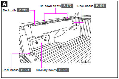
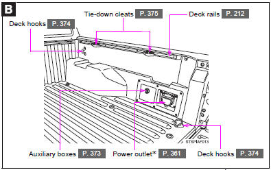
 Luggage compartment
*: If equipped ...

Other materials:
System Description
SYSTEM DESCRIPTION
1. ENGINE IMMOBILISER SYSTEM DESCRIPTION
The engine immobiliser system is designed to prevent the vehicle from being stolen.
This system uses the transponder key ECU assembly that stores the key ID codes of
authorized ignition keys. If an attempt is made to start the engine ...
Speed Signal Malfunction (B15C2)
DESCRIPTION
The navigation receiver assembly receives a vehicle speed signal from the combination
meter assembly and information from the navigation antenna assembly, and then adjusts
the vehicle position.
The navigation receiver assembly stores this DTC when the difference between
the speed ...
Engine Hood Courtesy Switch
Components
COMPONENTS
ILLUSTRATION
Inspection
INSPECTION
PROCEDURE
1. INSPECT HOOD COURTESY SWITCH (HOOD LOCK ASSEMBLY)
(a) Check the resistance.
(1) Measure the resistance according to the value(s) in the table below.
Text in Illustration
*a
...
