Toyota Tacoma (2015-2018) Service Manual: Front Crankshaft Oil Seal
Components
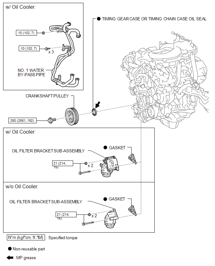
COMPONENTS
ILLUSTRATION
Installation
INSTALLATION
PROCEDURE
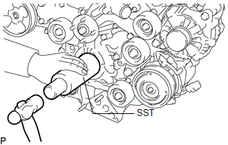
1. INSTALL TIMING GEAR CASE OR TIMING CHAIN CASE OIL SEAL
(a) Apply MP grease to the lip of a new timing gear case or timing chain case oil seal.
|
(b) Using SST and a hammer, tap in the timing gear case or timing chain case oil seal until its surface is flush with the timing chain cover edge. SST: 09226-10010 NOTICE:
|
|
2. INSTALL CRANKSHAFT PULLEY
.gif)
3. INSTALL OIL FILTER BRACKET SUB-ASSEMBLY (w/ Oil Cooler)
4. INSTALL OIL FILTER BRACKET SUB-ASSEMBLY (w/o Oil Cooler)
5. CONNECT NO. 1 WATER BY-PASS PIPE (w/ Oil Cooler)
6. INSTALL RADIATOR ASSEMBLY
(See page )
Removal
REMOVAL
PROCEDURE
1. REMOVE RADIATOR ASSEMBLY
(See page .gif) )
)
2. DISCONNECT NO. 1 WATER BY-PASS PIPE (w/ Oil Cooler)
3. REMOVE OIL FILTER BRACKET SUB-ASSEMBLY (w/ Oil Cooler)
4. REMOVE OIL FILTER BRACKET SUB-ASSEMBLY (w/o Oil Cooler)
5. REMOVE CRANKSHAFT PULLEY
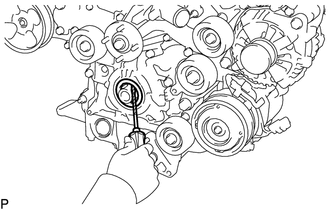
6. REMOVE TIMING GEAR CASE OR TIMING CHAIN CASE OIL SEAL
|
(a) Using a screwdriver, pry out the timing gear case or timing chain case oil seal. NOTICE: Do not damage the surface of the oil seal press fit hole or crankshaft. HINT: Tape the screwdriver tip before use. |
|
 Installation
INSTALLATION
PROCEDURE
1. INSTALL ENGINE COOLANT TEMPERATURE SENSOR
2. INSTALL ENGINE OIL PRESSURE SWITCH ASSEMBLY
3. INSTALL IGNITION COIL ASSEMBLY
4. INSTALL FUEL INJECTOR SEAL
5. ...

Other materials:
Vehicle data recordings
Your Toyota is equipped with several sophisticated computers that will record
certain data, such as: • Engine speed
• Accelerator status
• Brake status
• Vehicle speed
• Shift position (except manual transmission)
The recorded data varies according to the vehicle grade level and opt ...
How To Proceed With Troubleshooting
CAUTION / NOTICE / HINT
HINT:
The ECM of this system is connected to the CAN communication system.
Therefore, before starting troubleshooting, make sure to check that there
is no trouble in the CAN and multiplex communication system.
*: Use the Techstream.
PROCEDURE
...
Installation
INSTALLATION
PROCEDURE
1. INSTALL REAR DOOR GLASS SUB-ASSEMBLY
(a) Clean and shape the contact surface of the vehicle body.
Text in Illustration
*a
Adhesive
*b
Vehicle Body
(1) Using a ...
