Toyota Tacoma (2015-2018) Service Manual: Inspection
INSPECTION
PROCEDURE
1. INSPECT TIRES
(a) Check the tires for wear and proper inflation pressure.
Standard Cold Tire Inflation Pressure:
|
Tire Size |
Front Wheel kPa (kgf/cm2, psi) |
Rear Wheel kPa (kgf/cm2, psi) |
Spare Wheel kPa (kgf/cm2, psi) |
|---|---|---|---|
|
P245/75R16 109S |
220 (2.2, 32) |
220 (2.2, 32) |
220 (2.2, 32) |
|
P265/70R16 112T |
210 (2.1, 30) |
210 (2.1, 30) |
210 (2.1, 30) |
|
P265/65R17 110S |
200 (2.0, 29) |
200 (2.0, 29) |
200 (2.0, 29) |
|
P265/60R18 109H |
200 (2.0, 29) |
200 (2.0, 29) |
200 (2.0, 29) |
|
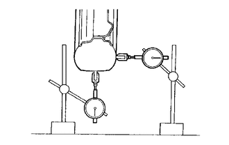
(b) Using a dial indicator, check the tire runout. Standard Tire Runout:
|
|
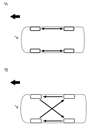
2. ROTATE TIRES
HINT:
Rotate the tires as shown in the illustration.
 Text in Illustration
|
*A |
for North America |
|
*B |
Except North America |
|
*a |
Overhead View |
.png) |
Front of Vehicle |
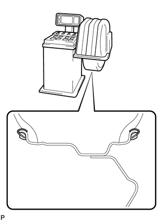
3. INSPECT WHEEL BALANCE
(a) Check and adjust the off-car balance.
|
(1) for Steel Wheel Type: Maximum imbalance after adjustment: 8.0 g (0.0176 lb) |
|
|
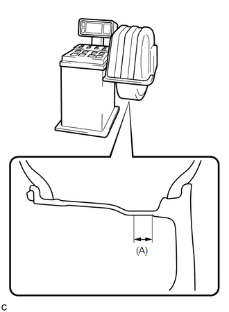
(2) for Aluminum Wheel Type: Maximum imbalance after adjustment: 8.0 g (0.0176 lb) NOTICE:
HINT: The inner side balance weight should be installed by clipping it to the rim. |
|
(b) If necessary, check and adjust the on-car balance.
Standard imbalance after adjustment:
8.0 g (0.0176 lb) or less
4. INSPECT FRONT AXLE HUB BEARING
.gif)
5. INSPECT REAR AXLE HUB BEARING
 How To Proceed With Troubleshooting
PROCEDURE
1.
CHECK TIRE AND WHEEL SYSTEM
DIAGNOSIS OF IRREGULAR TIRE WEAR
GO TO STEP 11
DIAGNOSIS OF TIRE VIBRATIO ...
 Precaution
PRECAUTION
1. REMOVAL AND INSTALLATION OF TIRE PRESSURE WARNING VALVE AND TRANSMITTER
(a) When installing a tire, make sure that the tire pressure warning valve and
transmitter does not interfere ...
Other materials:
Voice Guidance does not Function
PROCEDURE
1.
CHECK VOICE GUIDANCE SETTING
(a) Check that the voice guidance setting is not off.
OK:
Voice guidance setting is not off.
NG
CHANGE THE VOICE GUIDANCE SETTING TO ON
OK
...
Sun visors
Type A
Forward position: Flip down.
Side position: Flip down, unhook,
and swing to the side.
Type B
Forward position: Flip down.
Side position: Flip down, unhook,
and swing to the side.
Side extender: Place in side position,
then slide backwards. ...
Listening to Bluetooth¬Ѓ audio
The Bluetooth¬Ѓ audio system enables the user to enjoy music played on a portable
player from the vehicle speakers via wireless communication.
Select вАЬ AudioвАЭ on the вАЬSelect Audio SourceвАЭ screen.
When a Bluetooth¬Ѓ device cannot be connected, check the connection status on
the вАЬBluet ...
