Components
COMPONENTS
ILLUSTRATION
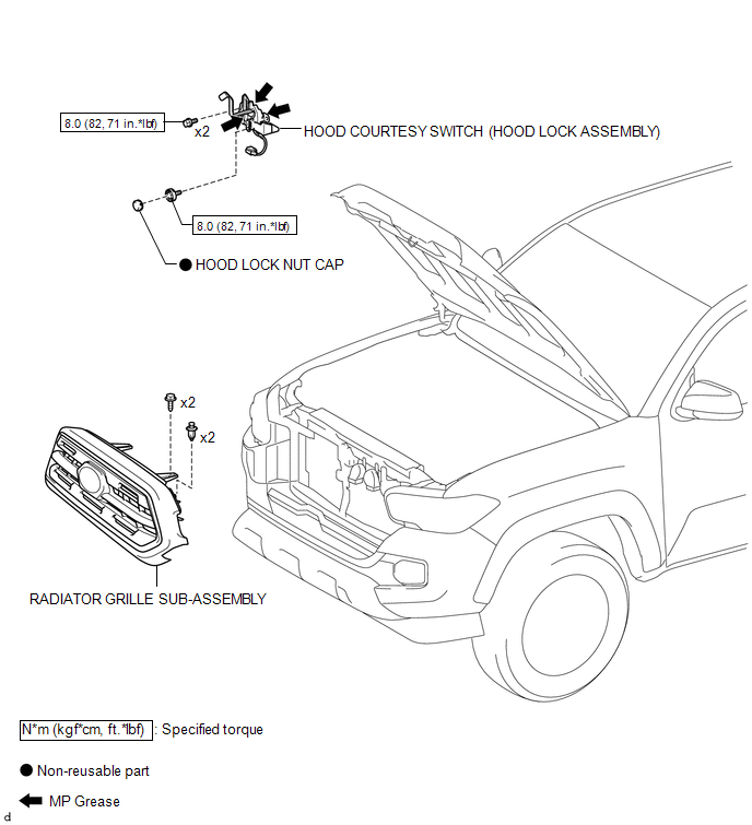
Inspection
INSPECTION
PROCEDURE
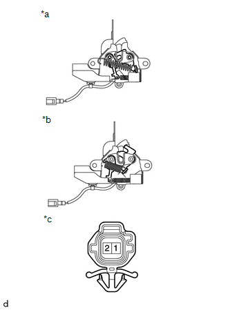
1. INSPECT HOOD COURTESY SWITCH (HOOD LOCK ASSEMBLY)
(a) Check the resistance.
|
(1) Measure the resistance according to the value(s) in the table below. Text in Illustration
Standard Resistance:
If the results are not as specified, replace the hood courtesy switch (hood lock assembly). |
|
Removal
REMOVAL
PROCEDURE
1. REMOVE RADIATOR GRILLE SUB-ASSEMBLY
(See page .gif) )
)
2. REMOVE HOOD COURTESY SWITCH (HOOD LOCK ASSEMBLY)
|
(a) Disconnect the connector. |
|
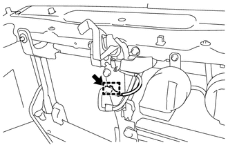
(b) Disengage the clamp to separate the wire harness.
|
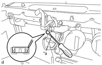
(c) Using a screwdriver with its tip wrapped in protective tape, remove the hood lock nut cap. Text in Illustration
|
|
|
(d) Remove the 3 bolts to separate the hood courtesy switch (hood lock assembly). |
|
.png)
|
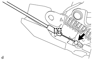
(e) Disengage the guide to disconnect the hood lock control cable assembly and remove the hood courtesy switch (hood lock assembly). |
|
Installation
INSTALLATION
PROCEDURE
1. INSTALL HOOD COURTESY SWITCH (HOOD LOCK ASSEMBLY)
|
(a) Apply MP grease to the sliding areas of the hood courtesy switch (hood lock assembly). |
|
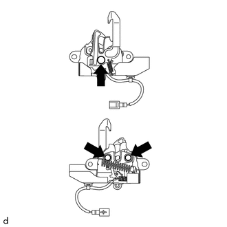
(b) Engage the guide to connect the hood lock control cable assembly.
(c) Install the hood courtesy switch (hood lock assembly) with the 3 bolts.
Torque:
8.0 N·m {82 kgf·cm, 71 in·lbf}
(d) Install a new hood lock nut cap.
(e) Connect the connector.
(f) Engage the clamp to install the wire harness.
2. ADJUST HOOD SUB-ASSEMBLY
(See page .gif) )
)
3. INSTALL RADIATOR GRILLE SUB-ASSEMBLY
(See page
)