Toyota Tacoma (2015-2018) Service Manual: ECU Power Source Circuit
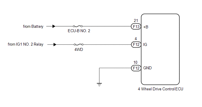
WIRING DIAGRAM
CAUTION / NOTICE / HINT
NOTICE:
Inspect the fuses for circuits related to this system before performing the following inspection procedure.
PROCEDURE
|
1. |
INSPECT BATTERY |
(a) Check the battery voltage.
Standard voltage:
11 to 14 V
| NG | .gif) |
CHECK OR REPLACE CHARGING SYSTEM OR BATTERY |
|
.gif)
|
2. |
CHECK HARNESS AND CONNECTOR (+B AND IG TERMINAL) |
(a) Turn the ignition switch off.
|
(b) Disconnect the 4 wheel drive control ECU connector. |
|
(c) Measure the voltage according to the value(s) in the table below.
Standard Voltage:
|
Tester Connection |
Switch Condition |
Specified Condition |
|---|---|---|
|
F13-21 (+B) - Body ground |
Always |
11 to 14 V |
|
F12-4 (IG) - Body ground |
Ignition switch ON |
11 to 14 V |
|
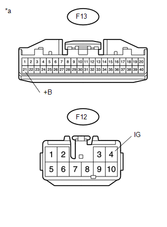
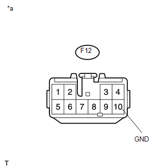
*a |
Front view of wire harness connector (to 4 Wheel Drive Control ECU) |
| NG | |
REPAIR OR REPLACE HARNESS OR CONNECTOR (+B AND IG CIRCUIT) |
|
|
3. |
CHECK HARNESS AND CONNECTOR (GND TERMINAL) |
(a) Turn the ignition switch off.
|
(b) Measure the resistance according to the value(s) in the table below. Standard Resistance:
|
|
| OK | |
PROCEED TO NEXT SUSPECTED AREA SHOWN IN PROBLEM SYMPTOMS TABLE |
| NG | |
REPAIR OR REPLACE HARNESS OR CONNECTOR (GND CIRCUIT) |
 4WD Control Switch Circuit
WIRING DIAGRAM
PROCEDURE
1.
CONFIRM PROBLEM SYMPTOM
(a) Confirm the problem symptoms.
Result
Result
Proceed to
The 4WD ind ...

Other materials:
Trailer Socket
Components
COMPONENTS
ILLUSTRATION
Removal
REMOVAL
PROCEDURE
1. REMOVE TRAILER SOCKET
(a) Disconnect the connector.
(b) Disengage the 2 clips to remove the trailer socket.
Install ...
Steering Angle Sensor Output Malfunction (C1434)
DESCRIPTION
Steering angle sensor signals are input to the skid control ECU (brake actuator
assembly) via the CAN communication system.
HINT:
When a malfunction occurs in the communication line to the steering angle sensor,
U0126 is output. If a DTC related to the CAN communication line is ou ...
Operation Check
OPERATION CHECK
1. CHECK POWER DOOR LOCK OPERATION
NOTICE:
The operation check below is based on the non-customized initial condition of
the vehicle.
(a) Check basic functions.
(1) Check that all doors lock when the lock side of the door control switch is
pressed.
(2) Check that all doors ...
