DESCRIPTION
If the entry lock and unlock functions do not operate for the driver door only, the request code may not be being transmitted from the driver door or the front door outside handle assembly LH (touch sensor) may be malfunctioning. If the entry functions for other doors operate properly, communication between the electrical key transmitter sub-assembly and electrical key and TPMS receiver assembly is normal.
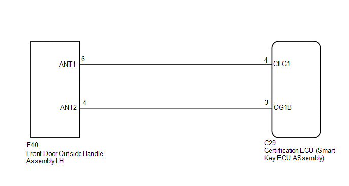
In this case, there may be a problem with request code transmission (communication between the certification ECU (smart key ECU assembly) and front door outside handle assembly LH [electrical key antenna]), or there may be wave interference.
HINT:
- If the driver door entry lock and unlock functions do not operate, the
cause of the malfunction may be stored in the certification ECU (smart key
ECU assembly) (See page
.gif) ).
). - If the cause of the malfunction is stored in the certification ECU (smart key ECU assembly), the following table is helpful in checking whether or not the malfunction was caused by wave interference.
|
Parameter Name |
Cause of Problem and Countermeasure |
|---|---|
|
Lock / Key RF Signal Interference |
When entry lock operation was performed, the electrical key transmitter sub-assembly could not be confirmed due to wave interference. If the cause of the malfunction has not been stored but the car has been moved and an entry lock operation has been successfully performed, the possibility of wave interference is high. |
|
Unlock / Key RF Signal Interference |
When entry unlock operation was performed, the electrical key transmitter sub-assembly could not be confirmed due to wave interference. If the cause of the malfunction has not been stored but the car has been moved and an entry unlock operation has been successfully performed, the possibility of wave interference is high. |
WIRING DIAGRAM
CAUTION / NOTICE / HINT
NOTICE:
- The smart key system (for Entry Function) uses a multiplex communication
system (LIN communication system) and the CAN communication system. Inspect
the communication function by following How to Proceed with Troubleshooting.
Troubleshoot the smart key system (for Entry Function) after confirming
that the communication systems are functioning properly (See page
).
- When using the Techstream with the engine switch off, connect the Techstream to the DLC3 and turn a courtesy light switch on and off at intervals of 1.5 seconds or less until communication between the Techstream and the vehicle begins. Then select the vehicle type under manual mode and enter the following menus: Body Electrical / Smart Key. While using the Techstream, periodically turn a courtesy light switch on and off at intervals of 1.5 seconds or less to maintain communication between the Techstream and the vehicle.
- Check that there are no electrical key transmitter sub-assemblies in the vehicle.
- Before performing the inspection, check that DTC B1242 (wireless door
lock control) is not output (See page ).
- Before replacing the certification ECU (smart key ECU assembly), refer
to the smart key system (for Entry Function) precaution (See page
).
- After repair, confirm that no DTCs are output by performing the "DTC Output Confirmation Operation".
PROCEDURE
|
1. |
CHECK POWER DOOR LOCK CONTROL SYSTEM |
(a) When the door control switch on the power window regulator master switch
assembly is operated, check that the doors unlock and lock according to the switch
operation (See page ).
OK:
Door locks operate normally.
| NG | .gif) |
GO TO POWER DOOR LOCK CONTROL SYSTEM |
|
.gif)
|
2. |
CHECK FOR DTC |
(a) Check for DTCs (See page ).
|
Result |
Proceed to |
|---|---|
|
DTCs are not output |
A |
|
DTCs are output |
B |
| B | |
GO TO DIAGNOSTIC TROUBLE CODE CHART |
|
|
3. |
CHECK WAVE ENVIRONMENT |
|
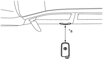
(a) Bring the electrical key transmitter sub-assembly approximately 0.3
m (0.984 ft.) from the front door outside handle assembly LH and perform
an entry function check (See page
HINT:
|
|
| B | |
AFFECTED BY WAVE INTERFERENCE |
|
|
4. |
READ VALUE USING TECHSTREAM (D-DOOR TOUCH SENSOR, D-DOOR TRIGGER SWITCH) |
(a) Connect the Techstream to the DLC3.
(b) Turn the engine switch on (IG).
(c) Turn the Techstream on.
(d) Enter the following menus: Body Electrical / Smart Key / Data List.
(e) Read the Data List according to the display on the Techstream.
Smart Key|
Tester Display |
Measurement Item/Range |
Normal Condition |
Diagnostic Note |
|---|---|---|---|
|
D-Door Touch Sensor |
Driver door touch sensor (unlock sensor) / ON or OFF |
ON: Driver door touch sensor (unlock sensor) touched OFF: Driver door touch sensor (unlock sensor) not touched |
|
|
D-Door Trigger Switch |
Driver door touch sensor (lock sensor) / ON or OFF |
ON: Driver door touch sensor (lock sensor) touched OFF: Driver door touch sensor (lock sensor) not touched |
|
HINT:
When checking the operation of the entry lock function several times, it can be operated up to 2 times consecutively. To operate the function 3 times or more consecutively, the doors need to be unlocked once. However, this is only for the entry lock function, other door lock operations, such as a wireless door lock operation can be performed consecutively.
OK:
The Techstream display changes correctly in response to the operation of the front door outside handle assembly LH.
| NG | |
GO TO STEP 6 |
|
|
5. |
CHECK KEY DIAGNOSTIC MODE |
(a) Check the following antenna in key diagnostic mode (See page
).
(b) Select either channel 1 or channel 2 and perform key diagnostic mode inspection for each channel.
|
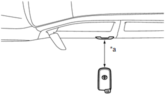
(1) Check the electrical key antenna (for driver door): When the electrical key transmitter sub-assembly is brought within 0.7 to 1 m (2.30 to 3.28 ft.) of the front door outside handle assembly LH, check that the wireless buzzer sounds. Text in Illustration
HINT:
|
|
| B | |
REPLACE CERTIFICATION ECU (SMART KEY ECU ASSEMBLY) |
|
|
6. |
CHECK HARNESS AND CONNECTOR (CERTIFICATION ECU (SMART KEY ECU ASSEMBLY) - FRONT DOOR OUTSIDE HANDLE ASSEMBLY LH) |
(a) Disconnect the C29 certification ECU (smart key ECU assembly) connector.
(b) Disconnect the F40 front door outside handle assembly LH connector.
(c) Measure the resistance according to the value(s) in the table below.
Standard Resistance:
|
Tester Connection |
Condition |
Specified Condition |
|---|---|---|
|
C29-4 (CLG1) - F40-6 (ANT1) |
Always |
Below 1 Ω |
|
C29-3 (CG1B) - F40-4 (ANT2) |
Always |
Below 1 Ω |
|
C29-4 (CLG1) or F40-6 (ANT1) - Body ground |
Always |
10 kΩ or higher |
|
C29-3 (CG1B) or F40-4 (ANT2) - Body ground |
Always |
10 kΩ or higher |
| NG | |
REPAIR OR REPLACE HARNESS OR CONNECTOR |
|
|
7. |
CHECK CERTIFICATION ECU (SMART KEY ECU ASSEMBLY) (OUTPUT TO DRIVER DOOR ELECTRICAL KEY ANTENNA) |
|
(a) Connect the C29 certification ECU (smart key ECU assembly) connector. |
|
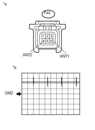
(b) Measure the voltage according to the value(s) in the table below.
OK:
|
Tester Connection |
Switch Condition |
Tool Setting |
Specified Condition |
|---|---|---|---|
|
F40-6 (ANT1) - F40-4 (ANT2) |
Procedure:
|
5 V/DIV., 100 ms/DIV. |
Pulse generation (See waveform 1) |
- *: For details about the entry function detection area, refer to Operation
Check (See page ).
|
*a |
Front view of wire harness connector (to Front Door Outside handle assembly LH) |
|
*b |
Waveform 1 |
| NG | |
REPLACE CERTIFICATION ECU (SMART KEY ECU ASSEMBLY) |
|
|
8. |
CHECK ENTRY LOCK OPERATION |
(a) Connect all connectors and check that the entry lock and unlock functions
operate (See page ).
|
Result |
Proceed to |
|---|---|
|
Entry function does not operate normally |
A |
|
Entry function operates normally |
B |
| B | |
END (CONNECTOR WAS NOT CONNECTED SECURELY) |
|
|
9. |
REPLACE FRONT DOOR OUTSIDE HANDLE ASSEMBLY LH |
(a) Temporarily replace the front door outside handle assembly LH with a new
or known good one (See page
).
|
|
10. |
CHECK ENTRY LOCK OPERATION |
(a) Check that the entry lock and unlock functions operate (See page
).
|
Result |
Proceed to |
|---|---|
|
Entry function operates normally |
A |
|
Entry function does not operate normally |
B |
| A | |
END (FRONT DOOR OUTSIDE HANDLE ASSEMBLY LH WAS DEFECTIVE) |
| B | |
REPLACE CERTIFICATION ECU (SMART KEY ECU ASSEMBLY) |