Toyota Tacoma (2015-2018) Service Manual: Components
COMPONENTS
ILLUSTRATION
|
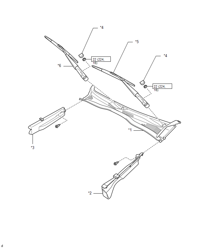
*1 |
COWL TOP VENTILATOR LOUVER SUB-ASSEMBLY |
*2 |
FRONT FENDER UPPER PROTECTOR LH |
|
*3 |
FRONT FENDER UPPER PROTECTOR RH |
*4 |
FRONT WIPER ARM HEAD CAP |
|
*5 |
WINDSHIELD WIPER ARM AND BLADE ASSEMBLY LH |
*6 |
WINDSHIELD WIPER ARM AND BLADE ASSEMBLY RH |
.png) |
N*m (kgf*cm, ft.*lbf): Specified torque |
- |
- |
ILLUSTRATION
ILLUSTRATION
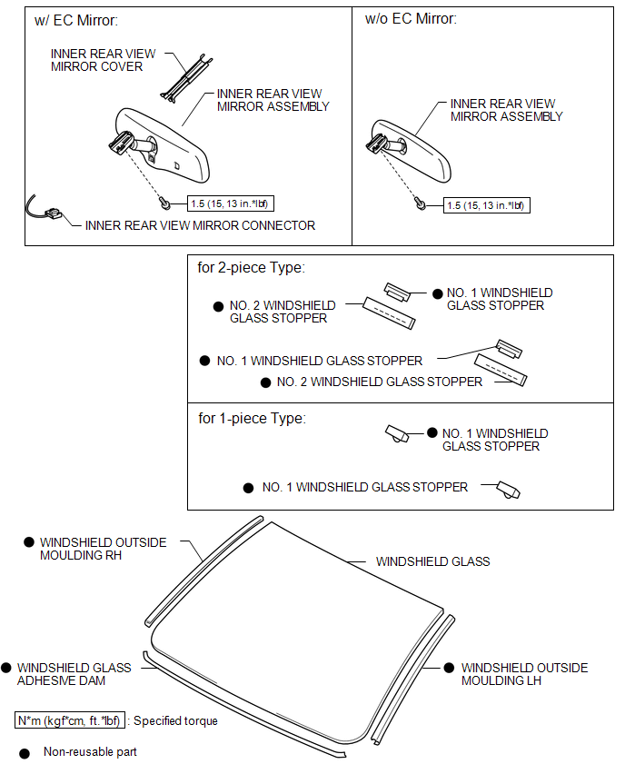
 Windshield Glass
...
 Removal
REMOVAL
CAUTION / NOTICE / HINT
NOTICE:
When replacing the windshield glass of a vehicle equipped with a forward recognition
camera, make sure to use a Toyota genuine part. If a non-Toyota genuin ...
Other materials:
Diagnostic Trouble Code Chart
DIAGNOSTIC TROUBLE CODE CHART
Forward Recognition Camera System
DTC No.
Detection Item
Link
C1A0A
Front Radar Sensor Region Code Mismatch
C1A47
Steering Angle Sensor
...
Precaution
PRECAUTION
1. IGNITION SWITCH EXPRESSIONS
(a) The type of ignition switch used on this model differs according to the specifications
of the vehicle. The expressions listed in the table below are used in this section.
Expression
Ignition Switch (Position)
Engine ...
On-vehicle Inspection
ON-VEHICLE INSPECTION
PROCEDURE
1. INSPECT FRONT AXLE HUB BEARING
(a) Remove the front wheel.
(b) for 4WD:
(1) Remove the front axle hub grease cap (See page
).
(c) Remove the front disc brake caliper (See page
).
(d) Remove the front disc.
(e) Inspect the axle hub backlash.
(1) Usi ...
