Toyota Tacoma (2015-2018) Service Manual: Components
COMPONENTS
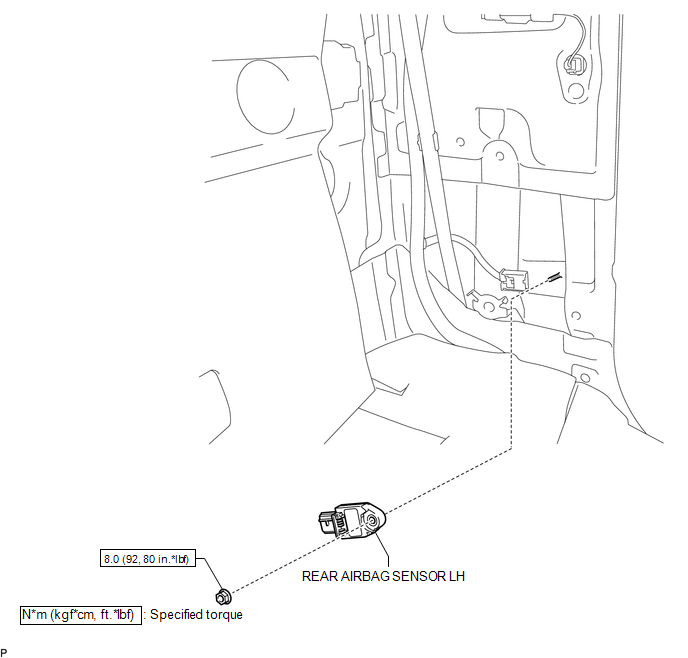
ILLUSTRATION

 On-vehicle Inspection
ON-VEHICLE INSPECTION
PROCEDURE
1. INSPECT REAR AIRBAG SENSOR (for Vehicle not Involved in Collision)
(a) Perform a diagnostic system check (See page
).
2. INSPECT REAR AIRBAG SENSOR (for Vehicl ...
Other materials:
Cellular Phone cannot Send/Receive
PROCEDURE
1.
CHECK "Bluetooth" SETTINGS
(a) Check if the cellular phone is registered as a connected device and the "Bluetooth"
settings are correct.
OK:
The cellular phone is registered as a connected device and "Bluetooth" settin ...
Reassembly
REASSEMBLY
CAUTION / NOTICE / HINT
NOTICE:
When installing, coat the parts indicated by the arrows with power steering fluid
(See page ).
PROCEDURE
1. INSTALL VANE PUMP HOUSING OIL SEAL
(a) Coat a new vane pump housing oil seal lip with power steering fluid.
(b) Using SST and a press, in ...
XM Tuner Antenna Disconnected (B15FE,B15FF)
DESCRIPTION
These DTCs are stored when a malfunction occurs in the antenna assembly with
holder which is connected to the navigation receiver assembly assembly.
DTC No.
DTC Detection Condition
Trouble Area
B15FE
The antenna assembly wi ...
