Toyota Tacoma (2015-2018) Service Manual: Components
COMPONENTS
ILLUSTRATION
|
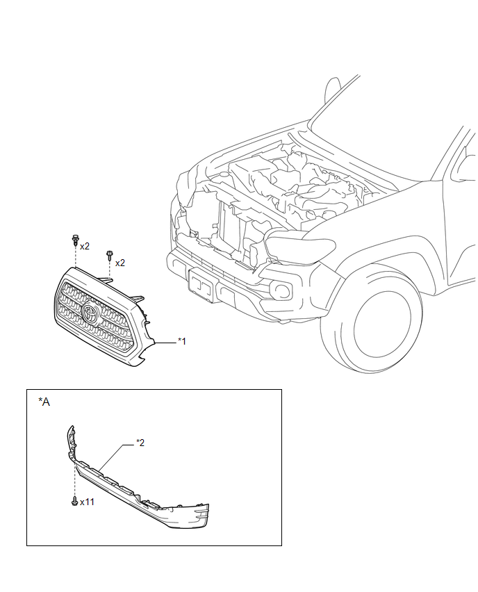
*A |
w/ Front Spoiler |
- |
- |
|
*1 |
RADIATOR GRILLE |
*2 |
FRONT NO. 1 WHEEL OPENING EXTENSION PAD |
ILLUSTRATION
|
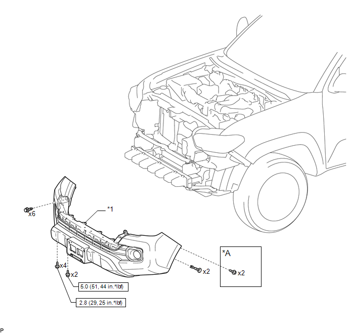
*A |
w/o Over Fender |
- |
- |
|
*1 |
FRONT BUMPER ASSEMBLY |
- |
- |
.png) |
N*m (kgf*cm, ft.*lbf): Specified torque |
- |
- |
ILLUSTRATION
|
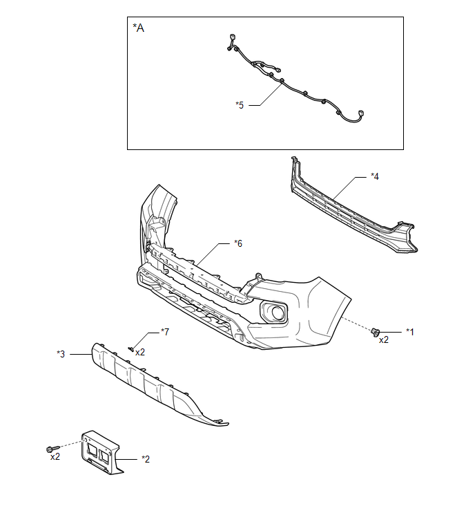
*A |
w/ Fog Light |
- |
- |
|
*1 |
FRONT FENDER LINER RETAINER |
*2 |
FRONT LICENSE PLATE BRACKET |
|
*3 |
FRONT VALANCE PANEL |
*4 |
LOWER NO. 1 RADIATOR GRILLE |
|
*5 |
NO. 4 ENGINE ROOM WIRE |
*6 |
FRONT BUMPER COVER |
|
*7 |
OUTSIDE MOULDING RETAINERS |
- |
- |
ILLUSTRATION
|
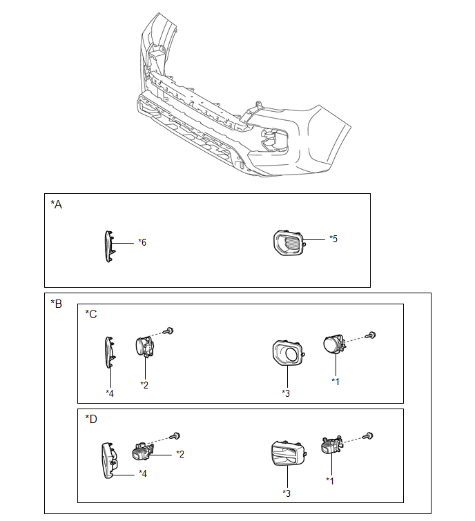
*A |
w/o Fog Light |
*B |
w/ Fog Light |
|
*C |
for Halogen Fog Light |
*D |
for LED Fog Light |
|
*1 |
FOG LIGHT ASSEMBLY LH |
*2 |
FOG LIGHT ASSEMBLY RH |
|
*3 |
FOG LIGHT COVER LH |
*4 |
FOG LIGHT COVER RH |
|
*5 |
FRONT BUMPER HOLE COVER LH |
*6 |
FRONT BUMPER HOLE COVER RH |
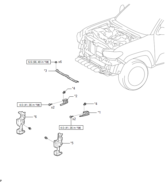
ILLUSTRATION
|
*1 |
FRONT BUMPER ARM MOUNTING BRACKET LH |
*2 |
FRONT BUMPER ARM MOUNTING BRACKET RH |
|
*3 |
FRONT BUMPER UPPER CENTER RETAINER |
*4 |
HEADLIGHT MOUNTING BRACKET |
|
*5 |
RADIATOR SIDE DEFLECTOR LH |
*6 |
RADIATOR SIDE DEFLECTOR RH |
|
|
N*m (kgf*cm, ft.*lbf): Specified torque |
- |
- |
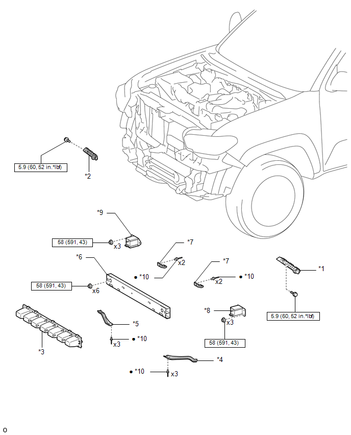
ILLUSTRATION
|
*1 |
FRONT BUMPER COVER INSERT LH |
*2 |
FRONT BUMPER COVER INSERT RH |
|
*3 |
FRONT BUMPER ENERGY ABSORBER |
*4 |
FRONT BUMPER INNER ARM SUB-ASSEMBLY LH |
|
*5 |
FRONT BUMPER INNER ARM SUB-ASSEMBLY RH |
*6 |
FRONT BUMPER REINFORCEMENT |
|
*7 |
LOWER FRONT BUMPER RETAINER |
*8 |
NO. 2 FRONT BUMPER EXTENSION SUB-ASSEMBLY LH |
|
*9 |
NO. 2 FRONT BUMPER EXTENSION SUB-ASSEMBLY RH |
*10 |
RIVET |
|
|
N*m (kgf*cm, ft.*lbf): Specified torque |
â—Ź |
Non-reusable part |
 Front Bumper
...
 Disassembly
DISASSEMBLY
PROCEDURE
1. REMOVE FRONT LICENSE PLATE BRACKET
(a) Remove the 2 screws and front license plate bracket.
2. REMOVE NO. 4 ENGINE ROO ...
Other materials:
Precaution
PRECAUTION
PRECAUTION FOR DISCONNECTING CABLE FROM NEGATIVE BATTERY TERMINAL
NOTICE:
When disconnecting the cable from the negative (-) battery terminal,
initialize the following systems after the cable is reconnected.
Click here
If the battery has been discharged and char ...
Operation Check
OPERATION CHECK
1. CHECK FUNCTION
(a) Check that the key reminder warning buzzer sounds.
(1) With the driver side door closed, insert the key into the ignition key cylinder
and then turn the key to LOCK or ACC.
(2) Check that the buzzer sounds intermittently when the driver side door is
open ...
Installation
INSTALLATION
PROCEDURE
1. INSTALL SPIRAL CABLE SUB-ASSEMBLY WITH SENSOR
(a) Check that the ignition switch is off.
(b) Check that the battery negative (-) terminal is disconnected.
CAUTION:
Wait at least 90 seconds after disconnecting the ca ...
