Toyota Tacoma (2015-2018) Service Manual: Components
COMPONENTS
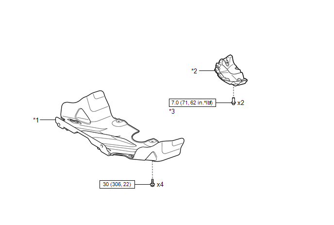
ILLUSTRATION
|
*1 |
NO. 1 ENGINE UNDER COVER SUB-ASSEMBLY |
*2 |
OIL PAN COVER SILENCER |
|
*3 |
NO. 1 OIL PAN PLUG |
- |
- |
.png) |
N*m (kgf*cm, ft.*lbf): Specified torque |
- |
- |
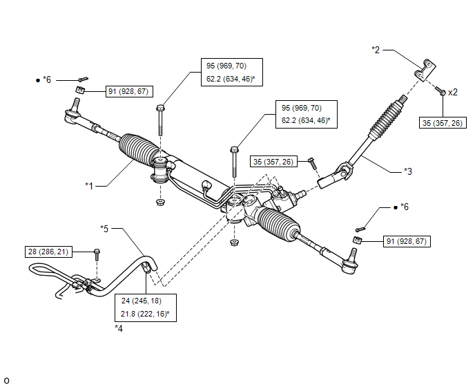
ILLUSTRATION
|
*1 |
POWER STEERING LINK |
*2 |
STEERING SLIDING YOKE |
|
*3 |
NO. 2 STEERING INTERMEDIATE SHAFT |
*4 |
PRESSURE FEED TUBE |
|
*5 |
RETURN HOSE |
*6 |
COTTER PIN |
|
|
N*m (kgf*cm, ft.*lbf): Specified torque |
* |
For use with SST or a union nut wrench |
|
â—Ź |
Non-reusable part |
- |
- |
ILLUSTRATION
.png)
ILLUSTRATION
.png)

 Disassembly
DISASSEMBLY
PROCEDURE
1. REMOVE STEERING GEAR OUTLET RETURN TUBE
(a) Using a union nut wrench, remove the steering gear outlet return tube.
2. REMOVE STEERING TURN PRESSURE TUBE
(a) Using a u ...
Other materials:
Fail-safe Chart
FAIL-SAFE CHART
If any of the following DTCs are stored, the ECM enters fail-safe mode to allow
the vehicle to be driven temporarily.
DTC
Fail-safe Operation
Fail-safe Deactivation Condition
P161A87
Generator command is maintained
...
Center Airbag Sensor Assembly Malfunction (B1000/31)
DESCRIPTION
The airbag sensor assembly consists of a deceleration sensor, safing sensor,
drive circuit, diagnosis circuit, ignition control, etc.
If the airbag sensor assembly receives signals from the deceleration sensor,
it determines whether or not the SRS should be activated.
DTC B1000/31 ...
Open in Bus 5 Main Bus Line
DESCRIPTION
There may be an open circuit in one of the CAN main bus lines when the resistance
between terminals 15 (CA5H) and 16 (CA5L) of the central gateway ECU (network gateway
ECU) is 70 Ω or higher.
Detection Item
Trouble Area
Resistance between ter ...
