Toyota Tacoma (2015-2018) Service Manual: Components
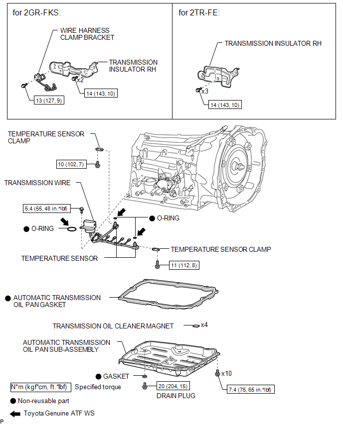
COMPONENTS
ILLUSTRATION

 Inspection
INSPECTION
PROCEDURE
1. INSPECT TRANSMISSION WIRE
(a) Measure the resistance according to the value(s) in the table below.
Text in Illustration
*a
...
Other materials:
Open in Occupant Classification ECU Battery Positive Line (B1794)
DESCRIPTION
DTC B1794 is set when a malfunction is detected in the occupant detection ECU.
DTC No.
DTC Detections Conditions
Trouble Areas
B1794
Occupant detection ECU circuit malfunction
Occupant detection ECU malfuncti ...
Automatic High Beam System (B124B)
DESCRIPTION
The main body ECU (multiplex network body ECU) determines the status of the automatic
high beam system based on the automatic high beam system signal from the forward
recognition camera.
DTC No.
Detection Item
DTC Detection Condition
Trou ...
Terminals Of Ecu
TERMINALS OF ECU
1. CHECK MAIN BODY ECU (MULTIPLEX NETWORK BODY ECU) AND DRIVER SIDE JUNCTION
BLOCK
(a) Disconnect the main body ECU (multiplex network body ECU) connectors.
Text in Illustration
*1
Main Body ECU (Multiplex Network Body ECU)
-
-
...
