Toyota Tacoma (2015-2018) Service Manual: Components
COMPONENTS
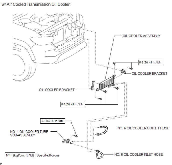
ILLUSTRATION
ILLUSTRATION
ILLUSTRATION
ILLUSTRATION
ILLUSTRATION

 Removal
REMOVAL
PROCEDURE
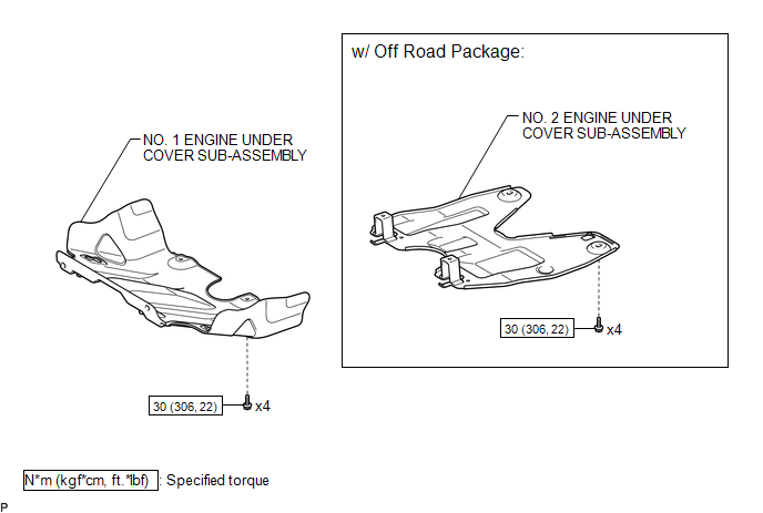
1. REMOVE NO. 2 ENGINE UNDER COVER SUB-ASSEMBLY (w/ Off Road Package)
2. REMOVE NO. 1 ENGINE UNDER COVER SUB-ASSEMBLY
3. DRAIN ENGINE COOLANT
4. REMOVE RADIATOR GRILLE
(See ...
Other materials:
Driver Side Power Window does not Operate with Power Window Master Switch
DESCRIPTION
When the engine is running or the ignition switch is ON, the front power window
regulator motor assembly LH is operated by the power window regulator master switch
assembly. The front power window regulator motor assembly LH has motor, regulator,
and ECU functions.
HINT:
If the ...
Brake Booster Pump Motor on Time Abnormally Long (C1252)
DESCRIPTION
The motor relay (semiconductor relay) is built into the master cylinder solenoid
and drives the pump motor based on a signal from the skid control ECU (master cylinder
solenoid).
DTC No.
DTC Detecting Condition
Trouble Areas
C1252
...
Terminals Of Ecm
TERMINALS OF ECM
1. ECM
HINT:
The standard voltage between each pair of ECM terminals is shown in the table
below. In the table, first follow the information under "Condition". Look under
"Terminal No. (Symbol)" for the terminals to be inspected. The standard voltage
b ...
