Toyota Tacoma (2015-2018) Service Manual: Combination Meter
Components
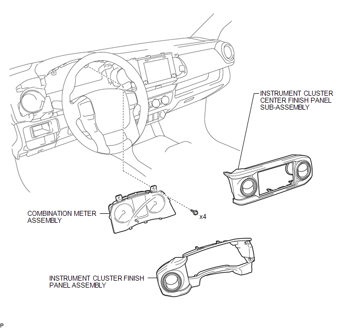
COMPONENTS
ILLUSTRATION
Removal
REMOVAL
PROCEDURE
1. PRECAUTION
NOTICE:
After turning the ignition switch off, waiting time may be required before disconnecting the cable from the negative (-) battery terminal. Therefore, make sure to read the disconnecting the cable from the negative (-) battery terminal notices before proceeding with work.
Click here .gif)
2. DISCONNECT CABLE FROM NEGATIVE BATTERY TERMINAL
NOTICE:
When disconnecting the cable, some systems need to be initialized after the cable is reconnected.
Click here
3. REMOVE INSTRUMENT CLUSTER CENTER FINISH PANEL SUB-ASSEMBLY
Click here
4. REMOVE INSTRUMENT CLUSTER FINISH PANEL ASSEMBLY
Click here
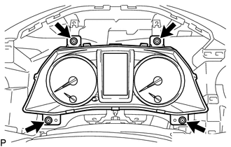
5. REMOVE COMBINATION METER ASSEMBLY
|
(a) Remove the 4 screws. |
|
|
(b) Disengage the clamp. |
|
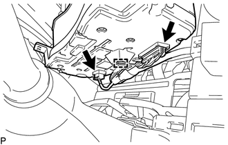
(c) Disconnect the 2 connectors to remove the combination meter assembly.
Installation
INSTALLATION
PROCEDURE
1. INSTALL COMBINATION METER ASSEMBLY
(a) Connect the 2 connectors.
(b) Engage the clamp.
(c) Install the combination meter assembly with the 4 screws.
2. INSTALL INSTRUMENT CLUSTER FINISH PANEL ASSEMBLY
Click here .gif)
3. INSTALL INSTRUMENT CLUSTER CENTER FINISH PANEL SUB-ASSEMBLY
Click here
4. CONNECT CABLE TO NEGATIVE BATTERY TERMINAL
Torque:
5.4 N·m {55 kgf·cm, 48 in·lbf}
NOTICE:
When disconnecting the cable, some systems need to be initialized after the cable is reconnected.
Click here


Other materials:
Other System Malfunction (C1A63)
DESCRIPTION
The millimeter wave radar sensor assembly receives accelerator pedal position
sensor signals from the ECM to determine if the accelerator pedal is being depressed.
If the ECM detects a malfunction in the accelerator pedal position sensor or SFI
system, the millimeter wave radar se ...
Rear Right Center Sensor Malfunction (C1AE8)
DESCRIPTION
The No. 1 ultrasonic sensor (rear center sensor RH) is installed on the rear
bumper. The ECU detects obstacles based on signals received from the No. 1 ultrasonic
sensor (rear center sensor RH). If the No. 1 ultrasonic sensor (rear center sensor
RH) has an open circuit or other ma ...
Disposal
DISPOSAL
CAUTION / NOTICE / HINT
CAUTION:
Before performing pre-disposal deployment of any SRS part, review and closely
follow all applicable environmental and hazardous material regulations. Predisposal
deployment may be considered hazardous material treatment.
PROCEDURE
1. PRECAUTION
...
