Toyota Tacoma (2015-2018) Service Manual: Clutch Master Cylinder
Components
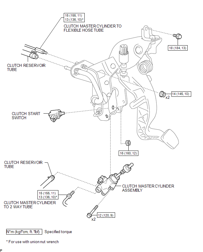
COMPONENTS
ILLUSTRATION
Installation
INSTALLATION
PROCEDURE
1. INSTALL CLUTCH MASTER CYLINDER ASSEMBLY
(a) Install the clutch master cylinder assembly to the clutch pedal support with the 2 bolts.
Torque:
12 N·m {120 kgf·cm, 9 ft·lbf}
(b) Install the clutch start switch to the clutch pedal support with the nut.
Torque:
16 N·m {160 kgf·cm, 12 ft·lbf}
(c) Using a union nut wrench, connect the clutch master cylinder to 2 way tube to the clutch master cylinder assembly.
Torque:
Specified tightening torque :
15 N·m {155 kgf·cm, 11 ft·lbf}
HINT:
- Calculate the torque wrench reading when changing the fulcrum length
of the torque wrench (See page
.gif) ).
). - When using a union nut wrench (fulcrum length of 22 mm (0.866 in.)) + torque wrench (fulcrum length of 162 mm (6.38 in.)): 13 N*m (136 kgf*cm, 10 ft.*lbf)
(d) Connect the clutch reservoir tube to the clutch master cylinder assembly.
2. INSTALL CLUTCH PEDAL WITH CLUTCH MASTER CYLINDER
(a) Install the clutch pedal with clutch master cylinder to the vehicle body with the bolt and 2 nuts.
Torque:
for Bolt :
18 N·m {184 kgf·cm, 13 ft·lbf}
for Nut :
14 N·m {145 kgf·cm, 10 ft·lbf}
(b) Connect the clutch switch connector.
(c) Connect the clutch start switch connector.
3. CONNECT CLUTCH MASTER CYLINDER TO FLEXIBLE HOSE TUBE
(a) Using a union nut wrench, connect the clutch master cylinder to flexible hose tube to the clutch pedal support way.
Torque:
Specified tightening torque :
15 N·m {155 kgf·cm, 11 ft·lbf}
HINT:
- Calculate the torque wrench reading when changing the fulcrum length
of the torque wrench (See page ).
- When using a union nut wrench (fulcrum length of 22 mm (0.866 in.)) + torque wrench (fulcrum length of 162 mm (6.38 in.)): 13 N*m (136 kgf*cm, 10 ft.*lbf)
4. CONNECT CLUTCH RESERVOIR TUBE
(a) Connect the clutch reservoir tube.
5. INSTALL DRIVER SIDE JUNCTION BLOCK
(See page )
6. FILL RESERVOIR WITH BRAKE FLUID
7. BLEED BRAKE LINE (for Vacuum Brake Booster)
8. BLEED CLUTCH LINE
9. INSPECT FOR CLUTCH FLUID LEAK
10. CHECK FLUID LEVEL IN RESERVOIR
11. INSPECT AND ADJUST CLUTCH PEDAL
Removal
REMOVAL
PROCEDURE
1. DRAIN CLUTCH FLUID
2. REMOVE DRIVER SIDE JUNCTION BLOCK
(See page .gif) )
)
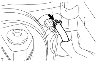
3. DISCONNECT CLUTCH RESERVOIR TUBE
|
(a) Disconnect the clutch reservoir tube. HINT: Use a container to collect the fluid. |
|
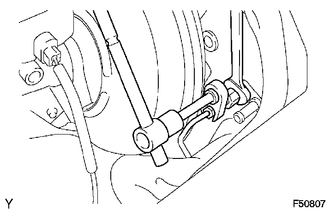
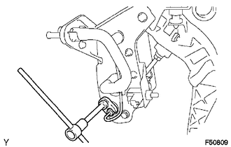
4. DISCONNECT CLUTCH MASTER CYLINDER TO FLEXIBLE HOSE TUBE
|
(a) Using a union nut wrench, disconnect the clutch master cylinder to flexible hose tube from the clutch pedal support way. HINT: Use a container to collect the fluid. |
|
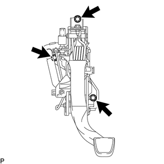
5. REMOVE CLUTCH PEDAL WITH CLUTCH MASTER CYLINDER
(a) Disconnect the clutch start switch connector.
(b) Disconnect the clutch switch connector.
|
(c) Remove the bolt, 2 nuts and clutch pedal with clutch master cylinder from the vehicle body. |
|
6. REMOVE CLUTCH MASTER CYLINDER ASSEMBLY
(a) Disconnect the clutch reservoir tube from the clutch master cylinder assembly.
|
(b) Using a union nut wrench, disconnect the clutch master cylinder to 2 way tube from the clutch master cylinder assembly. |
|
|
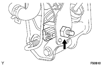
(c) Remove the nut and clutch start switch from the clutch pedal support. |
|
|
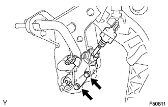
(d) Remove the 2 bolts and clutch master cylinder assembly from the clutch pedal support. |
|
 Clutch Accumulator
Components
COMPONENTS
ILLUSTRATION
Installation
INSTALLATION
PROCEDURE
1. INSTALL CLUTCH ACCUMULATOR ASSEMBLY
(a) Install the clutch accumulator assembly to the manual transmission assemb ...
 Clutch Pedal
...
Other materials:
Wireless Charger Illumination Circuit
DESCRIPTION
When the light control switch is turned to the tail or head position, this circuit
sends an illumination signal to the mobile wireless charger cradle assembly. Based
on this signal, the mobile wireless charger cradle assembly dims the indicator lights
(green and amber).
WIRING DI ...
Diagnosis System
DIAGNOSIS SYSTEM
1. DESCRIPTION
(a) The certification ECU (smart key ECU assembly) and ECM control the vehicle
engine immobiliser system functions. Engine immobiliser system data and Diagnostic
Trouble Codes (DTCs) can be read through the vehicle Data Link Connector 3 (DLC3).
In some cases, a ...
Parking Brake Switch Circuit
DESCRIPTION
This circuit is from the parking brake switch assembly to the navigation receiver
assembly.
WIRING DIAGRAM
PROCEDURE
1.
CHECK VEHICLE SIGNAL (OPERATION CHECK)
(a) Display the "Vehicle Signal Check Mode" screen (See page
). ...
