Toyota Tacoma (2015-2018) Service Manual: Camera Heater
Components
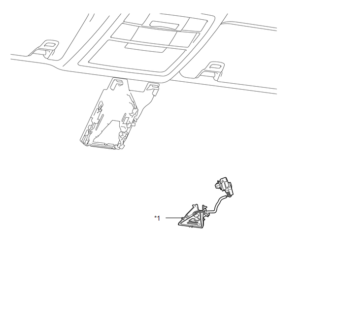
COMPONENTS
ILLUSTRATION
|
*1 |
FORWARD RECOGNITION WITH HEATER HOOD SUB-ASSEMBLY |
- |
- |
Removal
REMOVAL
PROCEDURE
1. REMOVE FORWARD RECOGNITION CAMERA
Click here .gif)
2. REMOVE FORWARD RECOGNITION WITH HEATER HOOD SUB-ASSEMBLY
NOTICE:
Do not touch the internal components of the forward recognition with heater hood sub-assembly or press on the heater when working on the forward recognition with heater hood sub-assembly.
|
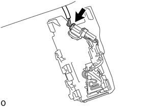
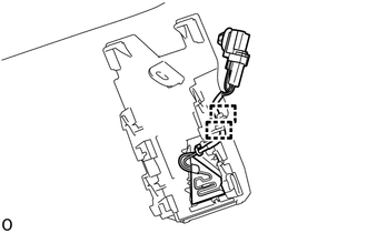
(a) Disconnect the connector. NOTICE: Do not pull the harness forcibly when disconnecting the connector. |
|
|
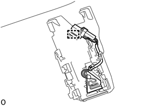
(b) Disengage the connector clamp. |
|
|
(c) Disengage the 2 guides to disconnect the wire harness. |
|
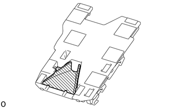
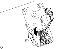
(d) Disengage the claw in the direction indicated by the arrow (1) in the illustration.
.png) |
Heater Area |
NOTICE:
Do not press the heater area.
(e) Disengage the guide in the direction indicated by the arrow (2) in the illustration to remove the forward recognition with heater hood sub-assembly.
Installation
INSTALLATION
PROCEDURE
1. INSTALL FORWARD RECOGNITION WITH HEATER HOOD SUB-ASSEMBLY
NOTICE:
Do not touch the internal components of the forward recognition with heater hood sub-assembly or press on the heater when working on the forward recognition with heater hood sub-assembly.
.png)
.png) |
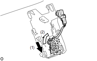
Heater Area |
(a) Engage the guide in the direction indicated by the arrow (1) in the illustration.
(b) Engage the claw in the direction indicated by the arrow (2) in the illustration.
NOTICE:
Do not press the heater area.
|
(c) Engage the 2 guides to connect the wire harness to the forward recognition bracket. |
|
.png)
|
(d) Engage the connector clamp to install the forward recognition with heater hood sub-assembly. |
|
.png)
|
(e) Connect the connector. |
|
.png)
2. INSTALL FORWARD RECOGNITION CAMERA
Click here .gif)
 Cruise Control
...
 Clutch Switch
Components
COMPONENTS
ILLUSTRATION
Removal
REMOVAL
PROCEDURE
1. PRECAUTION
NOTICE:
After turning the engine switch off, waiting time may be required before disconnecting
the cable from ...
Other materials:
Components
COMPONENTS
ILLUSTRATION
ILLUSTRATION
ILLUSTRATION
ILLUSTRATION
ILLUSTRATION
ILLUSTRATION
ILLUSTRATION
ILLUSTRATION
...
Initialization
INITIALIZATION
1. RESET MEMORY
NOTICE:
Perform Reset Memory (AT initialization) when replacing the automatic
transmission assembly, transmission valve body assembly or any of the shift
solenoid valves.
Reset Memory can be performed only with the Techstream.
HINT:
The E ...
Removal
REMOVAL
CAUTION / NOTICE / HINT
CAUTION:
Some of these service operations affect the SRS airbag system. Read the precautionary
notices concerning the SRS airbag system before servicing (See page
).
HINT:
Use the same procedure for both the RH and LH sides.
The procedure describe ...
