Toyota Tacoma (2015-2018) Service Manual: Blind Spot Monitor Main Switch
Components
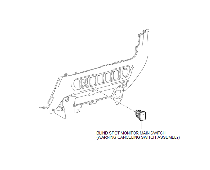
COMPONENTS
ILLUSTRATION
Removal
REMOVAL
PROCEDURE
1. REMOVE INSTRUMENT PANEL LOWER CENTER FINISH PANEL
(See page .gif) )
)
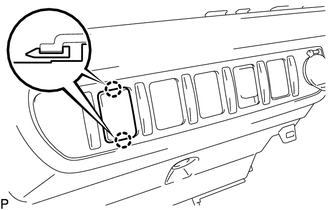
2. REMOVE BLIND SPOT MONITOR MAIN SWITCH (WARNING CANCELING SWITCH ASSEMBLY)
|
(a) Disengage the 2 claws to remove the blind spot monitor main switch (warning canceling switch assembly). |
|
Inspection
INSPECTION
PROCEDURE
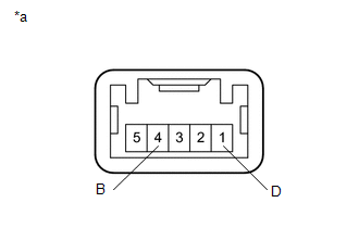
1. INSPECT BLIND SPOT MONITOR MAIN SWITCH (WARNING CANCELING SWITCH ASSEMBLY)
|
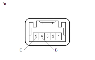
(a) Measure the resistance according to the value(s) in the table below. Text in Illustration
Standard Resistance:
If the result is not as specified, replace the blind spot monitor main switch (warning canceling switch assembly). |
|
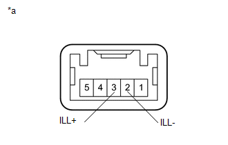
(b) Check that the switch illuminates.
|
(1) Apply battery voltage to the blind spot monitor main switch (warning canceling switch assembly) and check that the switch illuminates. Text in Illustration
OK:
If the result is not as specified, replace the blind spot monitor main switch (warning canceling switch assembly). |
|
(c) Check that the switch indicator operates.
|
(1) Apply battery voltage to the blind spot monitor main switch (warning canceling switch assembly) and check that the switch indicator operates. Text in Illustration
OK:
If the result is not as specified, replace the blind spot monitor main switch (warning canceling switch assembly). |
|
Installation
INSTALLATION
PROCEDURE
1. INSTALL BLIND SPOT MONITOR MAIN SWITCH (WARNING CANCELING SWITCH ASSEMBLY)
(a) Engage the 2 claws to install the blind spot monitor main switch (warning cancel switch assembly).
2. INSTALL INSTRUMENT PANEL LOWER CENTER FINISH PANEL
(See page .gif) )
)


Other materials:
Installation
INSTALLATION
PROCEDURE
1. INSTALL ROOF HEADLINING ASSEMBLY
(a) Insert the roof headlining assembly into the vehicle from the front
door RH side.
NOTICE:
Check that the corners of the roof headlining assembly are not
folded, twisted or otherwise deformed and ...
Problem Symptoms Table
PROBLEM SYMPTOMS TABLE
HINT:
Use the table below to help determine the cause of problem symptoms.
If multiple suspected areas are listed, the potential causes of the symptoms
are listed in order of probability in the "Suspected Area" column of the
table. Check each sy ...
Lost Communication with ECM / PCM "A" (U0100-U0142,U0155)
DESCRIPTION
These DTCs are stored when the clearance warning ECU assembly cannot receive
and recognize several signals via the CAN communication system.
DTC No.
DTC Detection Condition
Trouble Area
U0100
Lost Communication with ECM / P ...
