Toyota Tacoma (2015-2018) Service Manual: Parts Location
PARTS LOCATION
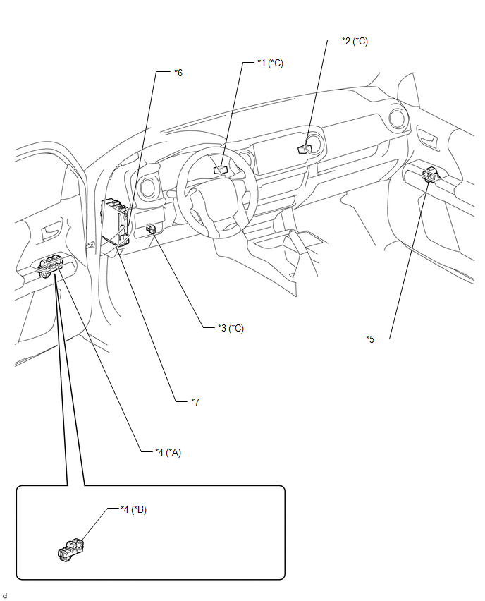
ILLUSTRATION
|
*A |
for Double Cab |
*B |
for Access Cab |
|
*C |
w/ Back Door Power Window |
- |
- |
|
*1 |
NO. 1 BACK PANEL RELAY |
*2 |
NO. 2 BACK PANEL RELAY |
|
*3 |
REAR NO. 2 POWER WINDOW REGULATOR SWITCH ASSEMBLY |
*4 |
POWER WINDOW REGULATOR MASTER SWITCH ASSEMBLY |
|
*5 |
FRONT POWER WINDOW REGULATOR SWITCH ASSEMBLY RH |
*6 |
MAIN BODY ECU(MULTIPLEX NETWORK BODY ECU) |
|
*7 |
DRIVER SIDE JUNCTION BLOCK - PWR RELAY - DOOR F/R FUSE - DOOR F/L FUSE - POWER NO. 1 FUSE - POWER NO. 2 FUSE |
- |
- |
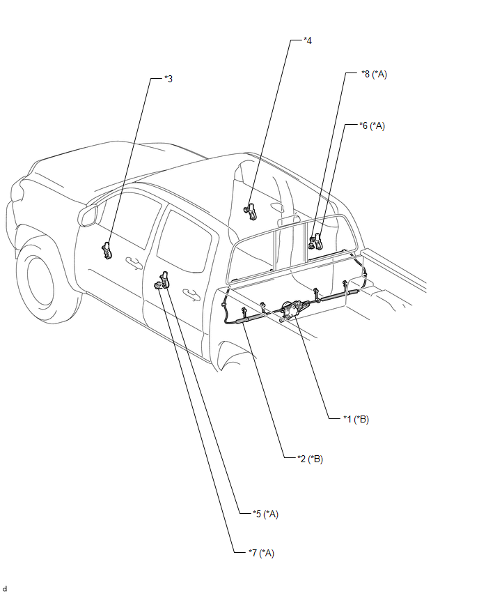
ILLUSTRATION
|
*A |
for Double Cab |
*B |
w/ Back Door Power Window |
|
*1 |
POWER WINDOW REGULATOR MOTOR ASSEMBLY |
*2 |
DOOR WINDOW REGULATOR CABLE SUB-ASSEMBLY |
|
*3 |
FRONT POWER WINDOW REGULATOR MOTOR ASSEMBLY LH |
*4 |
FRONT POWER WINDOW REGULATOR MOTOR ASSEMBLY RH |
|
*5 |
REAR POWER WINDOW REGULATOR MOTOR ASSEMBLY LH |
*6 |
REAR POWER WINDOW REGULATOR MOTOR ASSEMBLY RH |
|
*7 |
REAR POWER WINDOW REGULATOR SWITCH ASSEMBLY LH |
*8 |
REAR POWER WINDOW REGULATOR SWITCH ASSEMBLY RH |

 How To Proceed With Troubleshooting
CAUTION / NOTICE / HINT
HINT:
Use these procedures to troubleshoot the power window control system.
PROCEDURE
1.
VEHICLE BROUGHT TO WORK SHOP
...
Other materials:
Security Indicator Light Does not Blink
DESCRIPTION
The certification ECU (smart key ECU assembly) blinks the security indicator
light when the immobiliser is set (engine switch off, or driver door is
opened and closed with engine switch on (IG)).
The certification ECU (smart key ECU assembly) receive the security
...
Disposal
DISPOSAL
CAUTION / NOTICE / HINT
CAUTION:
Before performing pre-disposal deployment of any SRS part, review and closely
follow all applicable environmental and hazardous material regulations. Predisposal
deployment may be considered hazardous material treatment.
PROCEDURE
1. PRECAUTION
...
Pressure Control Solenoid "A" Performance (Shift Solenoid Valve SL1) (P0746)
SYSTEM DESCRIPTION
The ECM uses the vehicle speed signal and signals from the transmission revolution
sensors (NT, SP2) to detect the actual gear (1st, 2nd, 3rd, 4th, 5th or 6th gear).
The ECM compares the actual gear with the shift schedule in the ECM memory to
detect mechanical problems of t ...
