Toyota Tacoma (2015-2018) Service Manual: Transfer L4 Position Switch Circuit (C1268)
DESCRIPTION
A-TRAC is activated if wheel skid is detected while the transfer is in the L4 position.
|
DTC Code |
DTC Detecting Condition |
Trouble Areas |
|---|---|---|
|
C1268 |
L4 detection switch signal input to skid control ECU (master cylinder solenoid) does not match L4 detection switch signal output from ECM. |
|
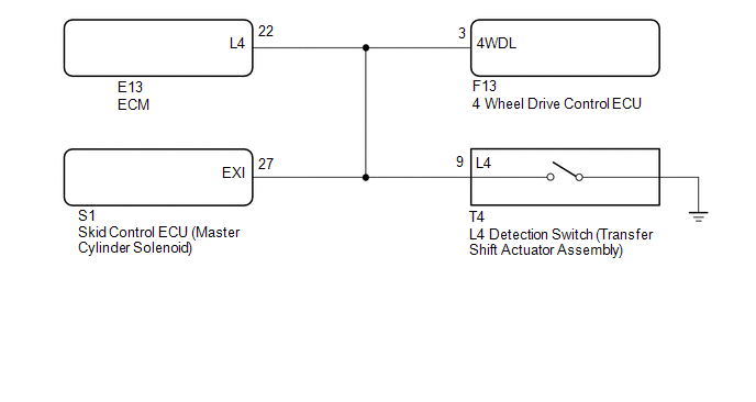
WIRING DIAGRAM
CAUTION / NOTICE / HINT
NOTICE:
When replacing the skid control ECU (master cylinder solenoid), perform zero
point calibration (See page .gif) ).
).
HINT:
When DTC U0114 is output together with DTC C1268, inspect and repair the trouble
areas indicated by DTC U0114 first (See page ).
PROCEDURE
|
1. |
INSPECT TOUCH SELECT 2-4 AND HIGH-LOW SYSTEM |
(a) Turn the 4WD control switch (transfer position switch) to L4, and then drive the vehicle and check that there are no problems with the touch select 2-4 and high-low system.
OK:
There are no problems with the touch select 2-4 and high-low system.
| NG | .gif) |
GO TO TOUCH SELECT 2-4 AND HIGH-LOW SYSTEM |
|
.gif)
|
2. |
CHECK HARNESS AND CONNECTOR (EXI TERMINAL) |
(a) Connect the S1 skid control ECU (master cylinder solenoid) connector.
(b) Turn the 4WD control switch (transfer position switch) to L4.
(c) Disconnect the E13 ECM connector.
|
(d) Disconnect the S1 skid control ECU (master cylinder solenoid) connector. |
|
(e) Measure the voltage according to the value(s) in the table below.
Standard Voltage:
|
Tester Connection |
Switch Condition |
Specified Condition |
|---|---|---|
|
S1-27 (EXI) - Body ground |
|
Below 1.5 V |
|
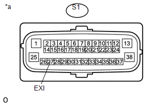
*a |
Front view of wire harness connector (to Skid Control ECU (Master Cylinder Solenoid)) |
(f) Reconnect the S1 skid control ECU (master cylinder solenoid) connector.
(g) Reconnect the E13 ECM connector.
(h) Turn the 4WD control switch (transfer position switch) to 2WD or H4.
(i) Disconnect the E13 ECM connector.
(j) Disconnect the S1 skid control ECU (master cylinder solenoid) connector.
(k) Measure the voltage according to the value(s) in the table below.
Standard Voltage:
|
Tester Connection |
Switch Condition |
Specified Condition |
|---|---|---|
|
S1-27 (EXI) - Body ground |
|
11 to 14 V |
| NG | |
REPAIR OR REPLACE HARNESS OR CONNECTOR (EXI TERMINAL) |
|
|
3. |
RECONFIRM DTC OUTPUT |
(a) Turn the ignition switch off.
(b) Reconnect the S1 skid control ECU (master cylinder solenoid) connector.
(c) Reconnect the E13 ECM connector.
(d) Turn the ignition switch to ON.
(e) Clear the DTC (See page
).
(f) Turn the ignition switch off.
(g) Start the engine.
(h) Turn the 4WD control switch (transfer position switch) to 2WD or H4.
(i) Turn the 4WD control switch (transfer position switch) to L4, drive the vehicle, and then check for DTCs.
Result|
Result |
Proceed to |
|---|---|
|
DTC is output |
A |
|
DTC is not output |
B |
| A | |
REPLACE MASTER CYLINDER SOLENOID |
| B | |
USE SIMULATION METHOD TO CHECK |
 Power Supply Drive Circuit (C1257)
DESCRIPTION
The motor relay (semiconductor relay) is built into the hydraulic brake booster
and drives the pump motor based on a signal from the skid control ECU (master cylinder
solenoid).
...
 Low Output Signal of Front Speed Sensor RH (Test Mode DTC) (C1271,C1272,C1401,C1402)
DESCRIPTION
The speed sensor detects the wheel speed and sends the appropriate signals to
the skid control ECU (master cylinder solenoid). These signals are used for brake
control.
The speed sen ...
Other materials:
Trailer Socket
Components
COMPONENTS
ILLUSTRATION
Removal
REMOVAL
PROCEDURE
1. REMOVE TRAILER SOCKET
(a) Disconnect the connector.
(b) Disengage the 2 clips to remove the trailer socket.
Install ...
Installation
INSTALLATION
PROCEDURE
1. SET NO. 1 CYLINDER TO TDC/COMPRESSION
2. INSTALL CAMSHAFT TIMING GEAR BOLT
NOTICE:
There are different types of camshaft timing gear bolts. Make sure to check the
identification mark to determine the tightening torque.
*a
Identification Ma ...
Parts Location
PARTS LOCATION
ILLUSTRATION
ILLUSTRATION
ILLUSTRATION
ILLUSTRATION
...
