Toyota Tacoma (2015-2018) Service Manual: Terminals Of Ecu
TERMINALS OF ECU
1. CHECK COMBINATION METER ASSEMBLY
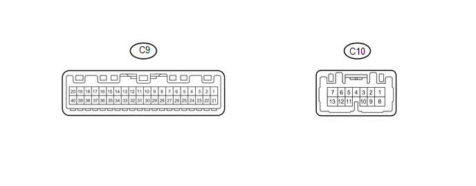
(a) Measure the resistance and voltage according to the value(s) in the table below.
|
Terminal No. (Symbol) |
Wiring Color |
Terminal Description |
Condition |
Specified Condition |
|---|---|---|---|---|
|
C9-19 (B) - Body ground |
P - Body ground |
Battery power supply |
Always |
11 to 14 V |
|
C9-20 (IG+) - Body ground |
BE - Body ground |
Ignition switch power supply |
Ignition switch ON |
11 to 14 V |
|
Ignition switch off |
Below 1 V |
|||
|
C9-17 (EP) - Body ground |
W-B - Body ground |
Ground |
Always |
Below 1 Ω |
|
C9-18 (ES) - Body ground |
W-B - Body ground |
Ground |
Always |
Below 1 Ω |
|
C9-1 (CANH) - Body ground |
G - Body ground |
CAN communication line |
Always |
200 Ω or higher |
|
C9-2 (CANL) - Body ground |
W - Body ground |
CAN communication line |
Always |
200 Ω or higher |
- If the result is not as specified, the combination meter assembly may have a malfunction.
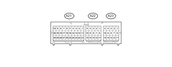
2. CHECK CENTER AIRBAG SENSOR ASSEMBLY
|
Terminal No. |
Terminal Symbol |
Destination |
|---|---|---|
|
A23-12 |
FSR+ |
Occupant classification ECU |
|
A23-13 |
FSR- |
Occupant classification ECU |
|
A22-11 |
LBE+ |
Front seat inner belt assembly (for driver side) |
|
A22-12 |
LBE- |
Front seat inner belt assembly (for driver side) |
3. CHECK OCCUPANT CLASSIFICATION ECU

(a) Measure the voltage and check for pulses according to the value(s) in the table below.
|
Terminal No. (Symbol) |
Wiring Color |
Terminal Description |
Condition |
Specified Condition |
|---|---|---|---|---|
|
O5-1 (+B) - O5-3 (GND) |
R - W-B |
Battery power supply |
Always |
11 to 14 V |
|
O5-2 (DIA) - O5-3 (GND) |
W - W-B |
Diagnosis (DLC3) |
Ignition switch ON |
Pulse generation |
|
O5-3 (GND) - Body ground |
W-B - Body ground |
Ground |
Always |
Below 1 V |
|
O5-7 (IG) - O5-3 (GND) |
BE - W-B |
Ignition switch power supply |
Ignition switch ON |
11 to 14 V |
|
O5-8 (FSR+) - O5-4 (FSR-) |
W - B |
Center airbag sensor assembly communication line |
Ignition switch ON |
Pulse generation |
|
O5-9 (BSW) - O5-5 (BGND) |
G - P-G |
Front passenger side buckle switch line |
Always |
4 to 14 V |
|
O4-1 (SGD1) - O5-3 (GND) |
L - W-B |
Front occupant classification sensor LH ground line |
Always |
Below 1 V |
|
O4-2 (SGD2) - O5-3 (GND) |
BE - W-B |
Front occupant classification sensor RH ground line |
Always |
Below 1 V |
|
O4-3 (SGD3) - O5-3 (GND) |
P-G - W-B |
Rear occupant classification sensor LH ground line |
Always |
Below 1 V |
|
O4-4 (SGD4) - O5-3 (GND) |
B-R - W-B |
Rear occupant classification sensor RH ground line |
Always |
Below 1 V |
|
O4-11 (SVC1) - O4-1 (SGD1) |
B-L - L |
Front occupant classification sensor LH power supply line |
Ignition switch ON, a load applied to front occupant classification sensor LH |
4.9 to 5.1 V |
|
O4-12 (SVC2) - O4-2 (SGD2) |
LG-B - BE |
Front occupant classification sensor RH power supply line |
Ignition switch ON, a load applied to front occupant classification sensor RH |
4.9 to 5.1 V |
|
O4-5 (SVC3) - O4-3 (SGD3) |
B - P-G |
Rear occupant classification sensor LH power supply line |
Ignition switch ON, a load applied to rear occupant classification sensor LH |
4.9 to 5.1 V |
|
O4-6 (SVC4) - O4-4 (SGD4) |
GR-L - B-R |
Rear occupant classification sensor RH power supply line |
Ignition switch ON, a load applied to rear occupant classification sensor RH |
4.9 to 5.1 V |
|
O4-7 (SIG1) - O4-1 (SGD1) |
G - L |
Front occupant classification sensor LH signal line |
Ignition switch ON, a load applied to front occupant classification sensor LH |
0 to 5.1 V |
|
O4-8 (SIG2) - O4-2 (SGD2) |
R-L - BE |
Front occupant classification sensor RH signal line |
Ignition switch ON, a load applied to front occupant classification sensor RH |
0 to 5.1 V |
|
O4-9 (SIG3) - O4-3 (SGD3) |
R-B - P-G |
Rear occupant classification sensor LH signal line |
Ignition switch ON, a load applied to rear occupant classification sensor LH |
0 to 5.1 V |
|
O4-10 (SIG4) - O4-4 (SGD4) |
L-R - B-R |
Rear occupant classification sensor RH signal line |
Ignition switch ON, a load applied to rear occupant classification sensor RH |
0 to 5.1 V |
- If the result is not as specified, the occupant classification ECU may have a malfunction.
 Problem Symptoms Table
PROBLEM SYMPTOMS TABLE
HINT:
Use the table below to help determine the cause of problem symptoms.
If multiple suspected areas are listed, the potential causes of the symptoms
are lis ...
 Driver Side Seat Belt Warning Light does not Operate
DESCRIPTION
When the ignition switch is ON, the airbag sensor assembly transmits front seat
inner belt status signals to the combination meter assembly through CAN. If the
driver seat belt is not ...
Other materials:
Customize Parameters
CUSTOMIZE PARAMETERS
PROCEDURE
1. CUSTOMIZE INTUITIVE PARKING ASSIST SYSTEM
(a) Customizing with the Techstream
NOTICE:
When the customer requests a change in a function, first make sure that
the function can be customized.
Be sure to make a note of the current settings before c ...
Removal
REMOVAL
PROCEDURE
1. PRECAUTION
NOTICE:
After turning the ignition switch off, waiting time may be required before disconnecting
the cable from the negative (-) battery terminal. Therefore, make sure to read the
disconnecting the cable from the negative (-) battery terminal notices before pr ...
Cleaning and protecting the vehicle interior
The following procedures will help protect your vehicle’s interior and keep
it in top condition:
■ Protecting the vehicle interior
Remove dirt and dust using a vacuum cleaner. Wipe dirty surfaces with a cloth
dampened with lukewarm water.
■ Cleaning the leather areas
● Re ...
