Toyota Tacoma (2015-2018) Service Manual: Terminals Of Ecu
TERMINALS OF ECU
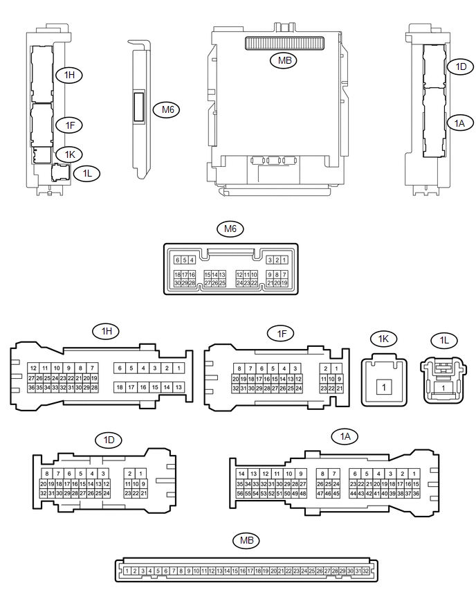
1. CHECK MAIN BODY ECU (MULTIPLEX NETWORK BODY ECU) AND DRIVER SIDE JUNCTION BLOCK
(a) Remove the main body ECU (multiplex network body ECU) from the driver side
junction block (See page .gif) ).
).
(b) Disconnect the 1D driver side junction block connector.
(c) Measure the voltage and resistance according to the value(s) in the table below.
|
Terminal No. (Symbol) |
Wiring Color |
Terminal Description |
Condition |
Specified Condition |
|---|---|---|---|---|
|
MB-11 (GND1) - Body ground |
None - Body ground |
Ground |
Always |
Below 1 Ω |
|
MB-31 (BECU) - Body ground |
None - Body ground |
Battery power supply |
Always |
11 to 14 V |
|
MB-30 (ACC) - Body ground |
None - Body ground |
ACC power supply |
Ignition switch ON(ACC) |
11 to 14 V |
|
MB-32 (IG) - Body ground |
None - Body ground |
Ignition switch power supply |
Ignition switch ON(IG) |
11 to 14 V |
|
1D-31 (KSW) - Body ground |
G - Body ground |
Unlock warning switch input |
No Key in ignition key cylinder (off) |
10 kΩ or higher |
|
Key inserted ignition key cylinder (on) |
Below 1 Ω |
(d) Install the main body ECU (multiplex network body ECU) to the driver side
junction block (See page ).
(e) Reconnect the 1D driver side junction block connector.
(f) Measure the voltage and check for pulse according to the value(s) in the table below.
|
Terminal No. (Symbol) |
Wiring Color |
Terminal Description |
Condition |
Specified Condition |
|---|---|---|---|---|
|
M6-6 (FLCY) - Body ground |
Y - Body ground |
Front door LH courtesy light switch input |
Front door LH open |
Below 1 V |
|
Front door LH closed |
Pulse generation |
|||
|
1D-31 (KSW) - Body ground |
G - Body ground |
Unlock warning switch input |
No Key in ignition key cylinder (off) |
11 to 14 V |
|
Key inserted ignition key cylinder (on) |
Below 1 V |
 Diagnosis System
DIAGNOSIS SYSTEM
1. CHECK DLC3
(a) Check the DLC3 (See page ).
2. INSPECT BATTERY VOLTAGE
(a) Measure the battery voltage.
Standard voltage:
11 to 14 V
If the voltage is below 11 V, replace t ...
 Key Reminder Buzzer does not Sound
DESCRIPTION
The key reminder warning buzzer sounds when the driver side door is opened while
the ignition switch is in the LOCK or ACC positions. The key reminder warning buzzer
is activated when ...
Other materials:
Side Moulding
Components
COMPONENTS
ILLUSTRATION
ILLUSTRATION
Removal
REMOVAL
CAUTION / NOTICE / HINT
HINT:
Use the same procedure for the RH side and LH side.
The following procedure is for the LH side.
When removing the lower No. 2 side panel moulding, heat the vehicle
body a ...
Installation
INSTALLATION
PROCEDURE
1. INSTALL TRANSMISSION FLOOR SHIFT ASSEMBLY
(a) Install the transmission floor shift assembly to the vehicle body with the
4 bolts.
Torque:
14 N·m {143 kgf·cm, 10 ft·lbf}
(b) Attach the 4 clamps to connect the wire harness to the transmission floor
shift assembl ...
Installation
INSTALLATION
CAUTION / NOTICE / HINT
HINT:
Use the same procedure for the RH side and LH side.
The procedure listed below is for the LH side.
PROCEDURE
1. INSTALL FRONT COIL SPRING
(a) Install SST to the front coil spring, and secure SST in a vise.
SST: 09727-00 ...
