Toyota Tacoma (2015-2018) Service Manual: System Diagram
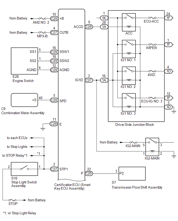
SYSTEM DIAGRAM
|
Component |
Outline |
|---|---|
|
Engine switch
|
|
|
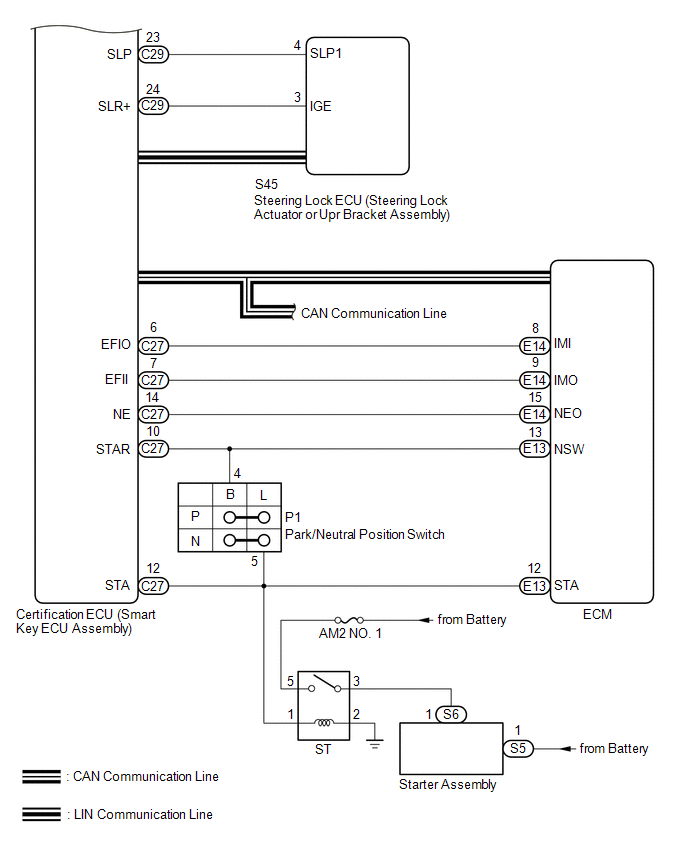
Certification ECU (smart key ECU assembly) |
|
|
ECM |
|
|
Steering lock ECU (steering lock actuator or UPR bracket assembly) |
|
|
Combination meter assembly |
|
|
IG, ACC relay |
Turns on/off according to the certification ECU (smart key ECU) and provides power to each system. |
|
Stop light switch assembly |
Detects that the brake pedal has been depressed (switch is on) and outputs a signal to the certification ECU (smart key ECU assembly). |
|
No. 1 indoor electrical key antenna assembly (front floor) No. 2 indoor electrical key antenna assembly (rear floor) |
Sends the request code from the certification ECU (smart key ECU assembly) and forms the vehicle interior detection area. |
|
Electrical key and TPMS receiver assembly |
Receives the smart key system code/wireless code sent from the key and sends it to the certification ECU (smart key ECU assembly). |
|
Electrical key transmitter sub-assembly |
Sends the ID code upon receiving a request signal. |
 Parts Location
PARTS LOCATION
ILLUSTRATION
ILLUSTRATION
ILLUSTRATION
ILLUSTRATION
...
 How To Proceed With Troubleshooting
CAUTION / NOTICE / HINT
HINT:
Use these procedures to troubleshoot the smart key system (for Start
Function).
*: Use the Techstream.
PROCEDURE
1.
VEHIC ...
Other materials:
Front Radar Sensor Region Code Mismatch (C1A0A)
DESCRIPTION
The forward recognition camera receives necessary information from the millimeter
wave radar sensor assembly.
When the forward recognition camera judges that a millimeter wave radar sensor
assembly which is not compatible with the vehicle has been installed, DTC C1A0A
is stored.
...
Fail-safe Chart
FAIL-SAFE CHART
If there is a problem with sensor signals or actuator systems, the skid
control ECU prohibits power supply to the brake actuator assembly and informs
the ECM of a VSC system malfunction.
The brake actuator assembly turns off the solenoids and the ECM stops
its ...
Components
COMPONENTS
ILLUSTRATION
*A
w/ Front Spoiler
-
-
*1
RADIATOR GRILLE
*2
FRONT NO. 1 WHEEL OPENING EXTENSION PAD
ILLUSTRATION
*A
w/o Over Fender
-
- ...
