Toyota Tacoma (2015-2018) Service Manual: System Diagram
SYSTEM DIAGRAM
 System Description
SYSTEM DESCRIPTION
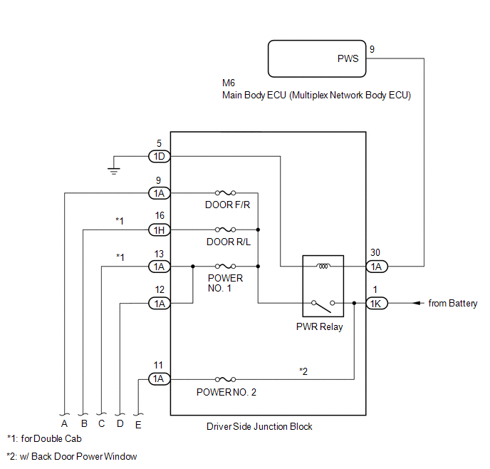
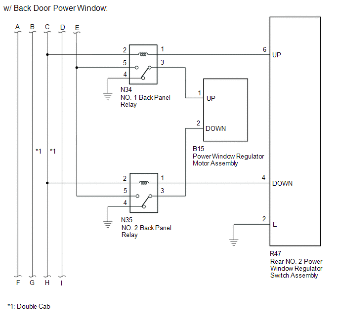
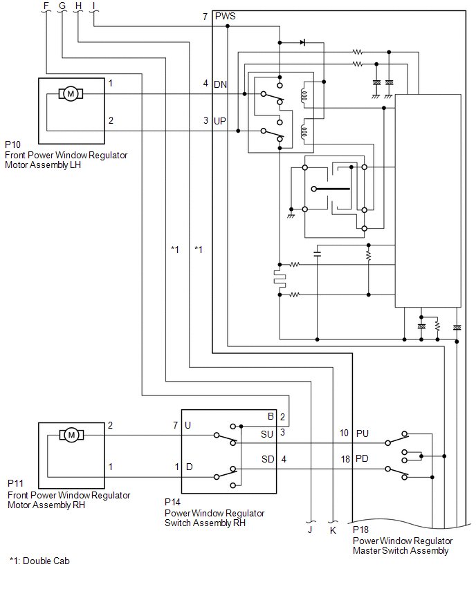
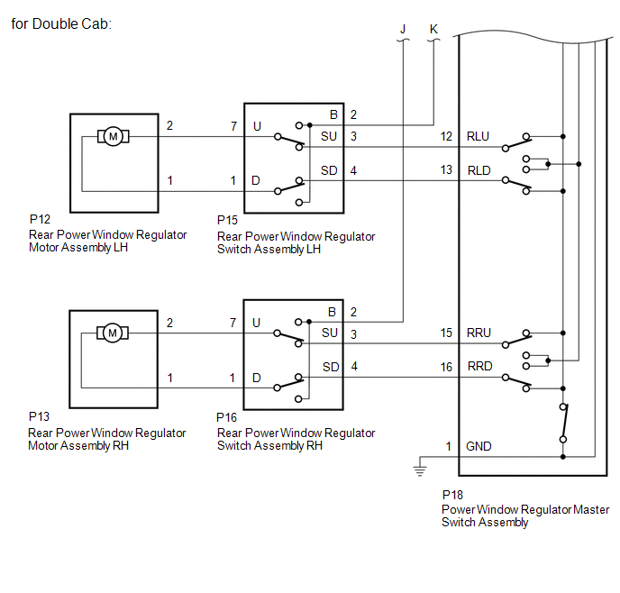
1. POWER WINDOW CONTROL SYSTEM DESCRIPTION
(a) The power window control system controls the power window operation using
the power window regulator motors. The main controls of ...
 Operation Check
OPERATION CHECK
1. CHECK WINDOW LOCK FUNCTION
(a) Turn the ignition switch ON.
(b) Press the window lock switch of the power window regulator master switch
assembly.
HINT:
The illumination (LED ...
Other materials:
How To Proceed With Troubleshooting
PROCEDURE
1.
VEHICLE BROUGHT TO WORKSHOP
NEXT
2.
CUSTOMER PROBLEM ANALYSIS
Click here
NEXT
...
Parts Location
PARTS LOCATION
ILLUSTRATION
*1
FUEL TANK CAP ASSEMBLY
*2
CHARCOAL CANISTER ASSEMBLY
*3
CHARCOAL CANISTER LEAK DETECTION PUMP SUB-ASSEMBLY
*4
PCV VALVE
*5
PURGE VSV
...
Parts Location
PARTS LOCATION
ILLUSTRATION
*A
for Vacuum Brake Booster
*B
for Hydraulic Brake Booster
*1
BRAKE ACTUATOR ASSEMBLY (SKID CONTROL ECU)
*2
BRAKE BOOSTER WITH MASTER CYLINDER ASSEMBLY (SKID CONTROL ECU)
...
