Toyota Tacoma (2015-2018) Service Manual: Removal
REMOVAL
CAUTION / NOTICE / HINT
HINT:
- Use the same procedure for both the RH and LH sides.
- The procedure described below is for the LH side.
PROCEDURE
1. PRECAUTION
CAUTION:
Be sure to read Precaution thoroughly before servicing (See page
.gif) ).
).
NOTICE:
After turning the ignition switch off, waiting time may be required before disconnecting the cable from the negative (-) battery terminal. Therefore, make sure to read the disconnecting the cable from the negative (-) battery terminal notices before proceeding with work.
Click here
2. DISCONNECT CABLE FROM NEGATIVE BATTERY TERMINAL
CAUTION:
Wait at least 90 seconds after disconnecting the cable from the negative (-) battery terminal to disable the SRS system.
NOTICE:
When disconnecting the cable, some systems need to be initialized after the cable is reconnected.
Click here
3. REMOVE ROOF HEADLINING ASSEMBLY
Click here
4. REMOVE CURTAIN SHIELD AIRBAG ASSEMBLY
|
(a) Using a screwdriver with its tip wrapped in protective tape, release the airbag connector lock. Text in Illustration
|
|
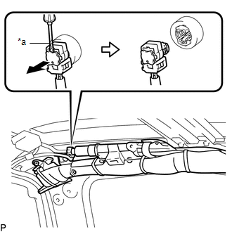
(b) Disconnect the connector.
NOTICE:
When handling the airbag connector, take care not to damage the airbag wire harness.
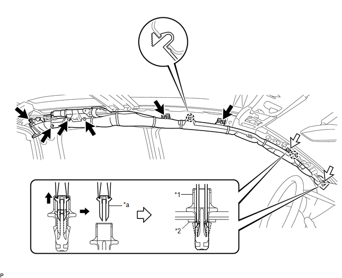
(c) Using needle nose pliers, remove the 2 pins from the 2 clips.
 Text in Illustration
|
*1 |
Clip |
*2 |
Spacer |
|
*a |
Pin |
- |
- |
HINT:
Remove the 2 clips and curtain shield airbag assembly from the vehicle body as a unit.
(d) While holding the curtain shield airbag assembly, remove the 6 bolts, disengage the 2 claws and remove the curtain shield airbag assembly.
(e) Remove the 2 clips and 2 spacers from the curtain shield airbag assembly.
 Installation
INSTALLATION
CAUTION / NOTICE / HINT
HINT:
Use the same procedure for both the RH and LH sides.
The procedure described below is for the LH side.
PROCEDURE
1. INSTALL CURTAIN SH ...

Other materials:
Brake Fluid(for Hydraulic Brake Booster)
On-vehicle Inspection
ON-VEHICLE INSPECTION
PROCEDURE
1. INSPECT FLUID LEVEL IN RESERVOIR
(a) Turn the ignition switch to OFF, and depress the brake pedal more
than 40 times (until the pedal reaction feels light and pedal stroke becomes
longer), and adjust the fluid level to ...
How To Proceed With Troubleshooting
CAUTION / NOTICE / HINT
HINT:
*: Use the Techstream.
PROCEDURE
1.
VEHICLE BROUGHT TO WORKSHOP
NEXT
2.
CUSTOMER PROBLEM ANALYSIS CHECK
HINT:
In troubleshooti ...
Freeze Frame Data
FREEZE FRAME DATA
1. CHECK FREEZE FRAME DATA
(a) Connect the Techstream to the DLC3.
(b) Turn the ignition switch to ON.
(c) Turn the Techstream on.
(d) Enter the following menus: Body Electrical / Navigation System / Trouble
Codes.
(e) Select a PTC to display its Freeze Frame Data.
2. LIST ...
