Toyota Tacoma (2015-2018) Service Manual: Short to +B in Outer Mirror Indicator(Master) (C1AB0)
DESCRIPTION
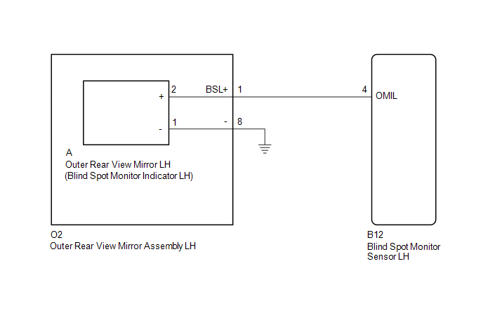
This DTC is stored when the blind spot monitor sensor LH detects a +B short in the blind spot monitor indicator LH.
|
DTC Code |
DTC Detection Condition |
Trouble Area |
|---|---|---|
|
C1AB0 |
With the blind spot monitor main switch assembly (warning canceling switch assembly) on, the voltage applied to the indicator is high for a certain amount of time even though the blind spot monitor sensor is not outputting voltage to the indicator. |
|
WIRING DIAGRAM
CAUTION / NOTICE / HINT
NOTICE:
When checking for DTCs, make sure that the blind spot monitor main switch assembly (warning canceling switch assembly) is on.
PROCEDURE
|
1. |
CHECK DTC |
(a) Clear the DTCs (See page .gif) ).
).
(b) Recheck for DTCs and check if the same DTC is output again (See page
).
OK:
No DTCs are output.
| OK | .gif) |
USE SIMULATION METHOD TO CHECK |
|
.gif)
|
2. |
CHECK HARNESS AND CONNECTOR (OUTER REAR VIEW MIRROR INDICATOR LH CIRCUIT) |
|
(a) Disconnect the blind spot monitor sensor LH connector. |
|
.png)
(b) Measure the voltage according to the value(s) in the table below.
Standard Voltage:
|
Tester Connection |
Switch Condition |
Specified Condition |
|---|---|---|
|
B12-4 (OMIL) - Body ground |
Ignition switch ON |
Below 1 V |
|
*a |
Front view of wire harness connector (to Blind Spot Monitor Sensor LH) |
| OK | |
REPLACE BLIND SPOT MONITOR SENSOR LH |
|
|
3. |
CHECK HARNESS AND CONNECTOR (BLIND SPOT MONITOR SENSOR LH - OUTER REAR VIEW MIRROR ASSEMBLY LH) |
|
(a) Disconnect the blind spot monitor sensor LH connector. |
|
(b) Disconnect the O2 outer rear view mirror assembly LH connector.
(c) Measure the voltage according to the value(s) in the table below.
Standard Voltage:
|
Tester Connection |
Switch Condition |
Specified Condition |
|---|---|---|
|
B12-4 (OMIL) - Body ground |
Ignition switch ON |
Below 1 V |
|
*a |
Front view of wire harness connector (to Blind Spot Monitor Sensor LH) |
| NG | |
REPAIR OR REPLACE HARNESS OR CONNECTOR |
|
|
4. |
CHECK HARNESS AND CONNECTOR (BLIND SPOT MONITOR SENSOR LH - OUTER REAR VIEW MIRROR LH) |
(a) Reconnect the O2 outer rear view mirror assembly LH connector.
|
(b) Disconnect the blind spot monitor sensor LH connector. |
|
(c) Disconnect the A outer rear view mirror LH connector.
(d) Measure the voltage according to the value(s) in the table below.
Standard Voltage:
|
Tester Connection |
Switch Condition |
Specified Condition |
|---|---|---|
|
B12-4 (OMIL) - Body ground |
Ignition switch ON |
Below 1 V |
|
*a |
Front view of wire harness connector (to Blind Spot Monitor Sensor LH) |
| OK | |
REPLACE OUTER REAR VIEW MIRROR LH |
| NG | |
REPLACE OUTER REAR VIEW MIRROR ASSEMBLY LH |
 Vehicle Speed Sensor (C1A45)
DESCRIPTION
The blind spot monitor sensor receives vehicle speed signals from the skid control
ECU (brake actuator assembly) via CAN communication.
DTC Code
DTC Detection Con ...
 Steering Angle Sensor (C1A47)
DESCRIPTION
The blind spot monitor sensor receives steering angle signals from the spiral
cable with sensor sub-assembly via CAN communication.
DTC Code
DTC Detection Conditi ...
Other materials:
All Doors LOCK/UNLOCK Functions do not Operate Via Door Control Switch or Door
Key Cylinder
DESCRIPTION
The main body ECU (multiplex network body ECU) receives switch signals from the
power window regulator master switch assembly and driver door key cylinder lock
or unlock switch signals from the front door lock assembly. The main body ECU (multiplex
network body ECU) activates the ...
On-vehicle Inspection
ON-VEHICLE INSPECTION
CAUTION / NOTICE / HINT
HINT:
Perform "Inspection After Repair" after replacing an ignition coil assembly or
spark plug (See page ).
PROCEDURE
1. PERFORM SPARK TEST
(a) Check for DTCs (See page ).
NOTICE:
If any DTC is output, perform the troubleshooting p ...
Data List / Active Test
DATA LIST / ACTIVE TEST
1. DATA LIST
NOTICE:
In the table below, the values listed under "Normal Condition" are reference
values. Do not depend solely on these reference values when deciding whether a part
is faulty or not.
HINT:
Using the Techstream to read the Data List allows t ...
