Toyota Tacoma (2015-2018) Service Manual: Seat Position Airbag Sensor Circuit Malfunction (B1653/35)
DESCRIPTION
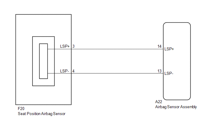
The seat position airbag sensor circuit consists of the airbag sensor assembly and the seat position airbag sensor.
DTC B1653/35 is stored when a malfunction is detected in the seat position airbag sensor assembly circuit.
|
DTC No. |
DTC Detection Condition |
Trouble Area |
|---|---|---|
|
B1653/35 |
|
|
WIRING DIAGRAM
CAUTION / NOTICE / HINT
NOTICE:
After turning the ignition switch off, waiting time may be required before disconnecting
the cable from the negative (-) battery terminal. Therefore, make sure to read the
disconnecting the cable from the negative (-) battery terminal notices before proceeding
with work (See page .gif) ).
).
PROCEDURE
|
1. |
CHECK CONNECTION OF CONNECTORS |
(a) Turn the ignition switch off.
(b) Disconnect the negative (-) terminal cable from the battery, and wait for at least 90 seconds.
(c) Check that the connectors are properly connected to the airbag sensor assembly and the seat position airbag sensor.
OK:
The connectors are properly connected.
| NG | .gif) |
CONNECT CONNECTORS |
|
.gif)
|
2. |
CHECK CONNECTORS |
(a) Disconnect the connector from the airbag sensor assembly.
(b) Disconnect the connector from the seat position airbag sensor.
(c) Check that the connectors (on the airbag sensor assembly side and seat position
airbag sensor side) are not damaged (See page
).
OK:
The connectors are not deformed or damaged.
|
Condition |
Proceed to |
|---|---|
|
Normal |
A |
|
Abnormal |
B |
| B | |
REPLACE HARNESS OR CONNECTOR |
|
|
3. |
CHECK NO. 2 FLOOR WIRE (AIRBAG SENSOR ASSEMBLY - SEAT POSITION AIRBAG SENSOR) |
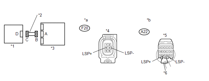 Text in Illustration
|
*1 |
Seat Position Airbag Sensor |
*2 |
No. 2 Floor Wire |
|
*3 |
Airbag Sensor Assembly |
*4 |
Connector C |
|
*5 |
Connector B |
*6 |
Service Wire |
|
*a |
Front view of wire harness connector (to Seat Position Airbag Sensor) |
*b |
Rear view of wire harness connector (to Airbag Sensor Assembly) |
(a) Connect the negative (-) terminal cable to the battery, and wait for at least 2 seconds.
(b) Turn the ignition switch to ON.
(c) Measure the voltage according to the value(s) in the table below.
Standard Voltage:
|
Tester Connection |
Switch Condition |
Specified Condition |
|---|---|---|
|
F20-3 (LSP+) - Body ground |
Ignition switch ON |
Below 1 V |
|
F20-4 (LSP-) - Body ground |
Ignition switch ON |
Below 1 V |
(d) Turn the ignition switch off.
(e) Disconnect the cable from the negative (-) battery terminal, and wait for at least 90 seconds.
(f) Using a service wire, connect terminals 13 (LSP-) and 14 (LSP+) of connector B.
NOTICE:
Do not forcibly insert the service wire into the terminals of the connector when connecting the wire.
(g) Measure the resistance according to the value(s) in the table below.
Standard Resistance:
|
Tester Connection |
Condition |
Specified Condition |
|---|---|---|
|
F20-3 (LSP+) - F20-4 (LSP-) |
Always |
Below 1 Ω |
(h) Disconnect the service wire from connector B.
(i) Measure the resistance according to the value(s) in the table below.
Standard Resistance:
|
Tester Connection |
Condition |
Specified Condition |
|---|---|---|
|
F20-3 (LSP+) - F20-4 (LSP-) |
Always |
1 MΩ or Higher |
|
F20-3 (LSP+) - Body ground |
Always |
1 MΩ or Higher |
|
F20-4 (LSP-) - Body ground |
Always |
1 MΩ or Higher |
| NG | |
REPLACE NO. 2 FLOOR WIRE |
|
|
4. |
CHECK SEAT POSITION AIRBAG SENSOR |
(a) Connect the connectors to the airbag sensor assembly.
(b) Connect the connector to the seat position airbag sensor.
(c) Connect the negative (-) terminal cable to the battery, and wait for at least 2 seconds.
(d) Turn the ignition switch to ON, and wait for at least 60 seconds.
(e) Clear any DTCs stored in the memory (See page
).
(f) Turn the ignition switch off.
(g) Turn the ignition switch to ON, and wait for at least 60 seconds.
(h) Check for DTCs (See page ).
OK:
DTC B1653/35 is not output.
HINT:
DTCs other than B1653/35 may be output at this time, but they are not related to this check.
| OK | |
USE SIMULATION METHOD TO CHECK |
|
|
5. |
REPLACE SEAT POSITION AIRBAG SENSOR |
(a) Turn the ignition switch off.
(b) Disconnect the cable from the negative (-) battery terminal, and wait for at least 90 seconds.
(c) Replace the seat position airbag sensor (See page
).
HINT:
Perform the inspection using parts from a normal vehicle when possible.
|
|
6. |
CHECK AIRBAG SENSOR ASSEMBLY |
(a) Connect the negative (-) terminal cable to the battery, and wait for at least 2 seconds.
(b) Turn the ignition switch to ON, and wait for at least 60 seconds.
(c) Clear the DTCs (See page ).
(d) Turn the ignition switch off.
(e) Turn the ignition switch to ON, and wait for at least 60 seconds.
(f) Check for DTCs (See page ).
OK:
DTC B1653/35 is not output.
HINT:
DTCs other than B1653/35 may be output at this time, but they are not related to this check.
| OK | |
END |
| NG | |
REPLACE AIRBAG SENSOR ASSEMBLY |
 Occupant Classification System Malfunction (B1650/32)
DESCRIPTION
The occupant classification system circuit consists of the airbag sensor assembly
and the occupant classification system.
When the airbag sensor assembly receives signals from the occu ...
 Side Airbag Sensor LH Circuit Malfunction (B1625/22)
DESCRIPTION
The side airbag sensor assembly LH consists of parts such as the safing sensor,
the diagnostic circuit and the lateral deceleration sensor.
When the airbag sensor assembly receives sig ...
Other materials:
Diagnosis System
DIAGNOSIS SYSTEM
1. DESCRIPTION
(a) Sliding roof system data and Diagnostic Trouble Codes (DTCs) can be read
through the vehicle Data Link Connector 3 (DLC3). When the system seems to be malfunctioning,
use the Techstream to check for malfunctions and perform repairs.
2. CHECK DLC3
(a) Check ...
Satellite Radio Tuner
Components
COMPONENTS
ILLUSTRATION
Removal
REMOVAL
PROCEDURE
1. REMOVE RADIO AND DISPLAY RECEIVER ASSEMBLY WITH BRACKET
(See page )
2. REMOVE NO. 1 NAVIGATION WIRE
(a) Disconnect the 6 connectors to remove the No. 1 navigation wire.
...
Driver Side Power Window Auto Up / Down Function does not Operate with Power
Window Master Switch
DESCRIPTION
If the manual up/down function can be performed but the auto up/down function
cannot, then the fail-safe mode may be functioning.
If the power window initialization (See page
) has not been performed, the auto up/down function will not operate.
WIRING DIAGRAM
CAUTION / NOTICE ...
