Toyota Tacoma (2015-2018) Service Manual: Removal
REMOVAL
CAUTION / NOTICE / HINT
NOTICE:
Replace the blind spot monitor sensor if it has been dropped or subjected to a severe impact.
PROCEDURE
1. REMOVE REAR BUMPER ASSEMBLY (w/ Towing Package)
(See page .gif) )
)
2. REMOVE REAR BUMPER ASSEMBLY (w/o Towing Package)
(See page )
3. REMOVE CONNECTOR COVER (w/ Towing Package)
(See page )
4. REMOVE REAR BUMPER HOLE COVER (w/o Towing Package)
(See page )
5. REMOVE REAR BUMPER PAD SUB-ASSEMBLY (w/ Towing Package)
(See page )
6. REMOVE REAR BUMPER PAD SUB-ASSEMBLY (w/o Towing Package)
(See page )
7. REMOVE REAR BUMPER EXTENSION LH (w/ Towing Package)
(See page )
8. REMOVE REAR BUMPER EXTENSION LH (w/o Towing Package)
(See page )
9. REMOVE REAR BUMPER EXTENSION RH (w/ Towing Package)
HINT:
Use the same procedure as for the LH side.
10. REMOVE REAR BUMPER EXTENSION RH (w/o Towing Package)
HINT:
Use the same procedure as for the LH side.
11. REMOVE BLIND SPOT MONITOR SENSOR LH
|
(a) Disconnect the connector. |
|
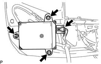
(b) Remove the 3 nuts and blind spot monitor sensor LH.
12. REMOVE BLIND SPOT MONITOR SENSOR RH
HINT:
Use the same procedure as for the LH side.
 Components
COMPONENTS
ILLUSTRATION
ILLUSTRATION
...
 Installation
INSTALLATION
CAUTION / NOTICE / HINT
NOTICE:
Replace the blind spot monitor sensor if it has been dropped or subjected to
a severe impact.
PROCEDURE
1. INSTALL BLIND SPOT MONITOR SENSOR LH
(a) ...
Other materials:
General maintenance
Listed below are the general maintenance items that should be performed at
the intervals specified in the “Scheduled Maintenance Guide” or “Owner’s Manual
Supplement”. It is recommended that any problem you notice should be brought to
the attention of your Toyota dealer or qualified ...
Diagnostic Trouble Code Chart
DIAGNOSTIC TROUBLE CODE CHART
Dynamic Radar Cruise Control System
DTC No.
Detection Item
MIL
Link
C1A02
Vehicle Information Not Obtained
Does not come on
C1A0A
Front Radar Se ...
Installation
INSTALLATION
PROCEDURE
1. INSTALL INSTRUMENT PANEL PASSENGER AIRBAG ASSEMBLY WITHOUT DOOR
(a) Engage the 3 hooks (B).
Text in Illustration
*a
Hooks (A)
*b
Hooks (B)
...
