Toyota Tacoma (2015-2018) Service Manual: System Diagram
SYSTEM DIAGRAM
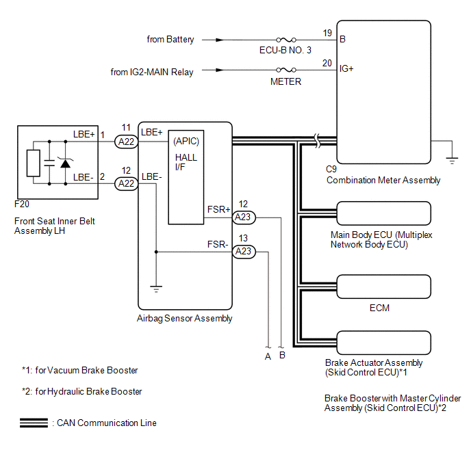
 Communication Table
|
Sender |
Receiver |
Signal |
Communication Method |
|---|---|---|---|
|
Airbag sensor assembly |
Main body ECU |
Front seat inner belt assembly LH buckle switch |
CAN |
|
Combination meter assembly |
|
||
|
Main body ECU |
Combination meter assembly |
Front seat inner belt assembly LH buckle switch |
|
|
Brake actuator assembly (Skid control ECU) |
Combination meter assembly |
Vehicle speed |
|
|
ECM |
Combination meter assembly |
Shift position |
 Precaution
PRECAUTION
1. IGNITION SWITCH EXPRESSIONS
(a) The type of ignition switch used on this model differs according to the specifications
of the vehicle. The expressions listed in the table below are u ...
 Customize Parameters
CUSTOMIZE PARAMETERS
1. CUSTOMIZE FUNCTION WITH TECHSTREAM
NOTICE:
Be sure to record the current settings before customizing.
These buzzers should be ON for safe driving. Perform these ...
Other materials:
Reassembly
REASSEMBLY
PROCEDURE
1. INSTALL UN-LOCK WARNING SWITCH ASSEMBLY (w/o Smart Key System)
(a) Engage the 2 claws to install the un-lock warning switch assembly to the
upper steering column bracket assembly.
2. INSTALL IGNITION SWITCH LOCK CYLINDER ASSEMBLY (w/o Smart Key System)
(a) T ...
Transfer System
Precaution
PRECAUTION
Before disassembly, clean the transfer assembly and remove any deposited
sand and mud to prevent it from entering the transfer during disassembly
and assembly.
When removing any light alloy parts such as the transfer covers, do
not pry them off with a ...
Rear view monitor system
The rear view monitor system assists the driver by displaying guide lines and
an image of the view behind the vehicle while backing up, for example while parking.
The screen illustrations used in this text are intended as examples, and may
differ from the image that is actually displayed on the ...
