Toyota Tacoma (2015-2018) Service Manual: Removal
REMOVAL
CAUTION / NOTICE / HINT
CAUTION:
Some of these service operations affect the SRS airbag system. Read the precautionary
notices concerning the SRS airbag system before servicing (See page
.gif) ).
).
HINT:
- Use the same procedure for both the RH and LH sides.
- The procedure described below is for the LH side.
PROCEDURE
1. PRECAUTION
CAUTION:
Be sure to read Precaution thoroughly before servicing (See page
).
NOTICE:
After turning the ignition switch off, waiting time may be required before disconnecting the cable from the negative (-) battery terminal. Therefore, make sure to read the disconnecting the cable from the negative (-) battery terminal notices before proceeding with work.
Click here
2. DISCONNECT CABLE FROM NEGATIVE BATTERY TERMINAL
CAUTION:
Wait at least 90 seconds after disconnecting the cable from the negative (-) battery terminal to disable the SRS system.
NOTICE:
When disconnecting the cable, some systems need to be initialized after the cable is reconnected.
Click here
3. REMOVE FRONT DOOR SCUFF PLATE
4. REMOVE REAR DOOR SCUFF PLATE
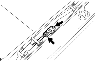
5. REMOVE SIDE AIRBAG SENSOR ASSEMBLY
(a) Disconnect the connector from the side airbag sensor.
NOTICE:
When disconnecting any airbag connector, take care not to damage the airbag wire harness.
(1) Push and hold the white housing lock, and slide the yellow outer connector locking sleeve.
.png)
(2) Push and hold the white housing lock again, and slide the yellow outer connector locking sleeve to disconnect the connector.
(b) Remove the bolt and side airbag sensor.
NOTICE:
Loosen the bolt while holding the door side airbag sensor because the side airbag sensor pin (stopper) is easily damaged.
 Installation
INSTALLATION
CAUTION / NOTICE / HINT
CAUTION:
Some of these service operations affect the SRS airbag system. Read the precautionary
notices concerning the SRS airbag system before servicing (See ...

Other materials:
Data List / Active Test
DATA LIST / ACTIVE TEST
1. DATA LIST
NOTICE:
In the table below, the values listed under "Normal Condition" are reference
values. Do not depend solely on these reference values when deciding whether a part
is faulty or not.
HINT:
Using the Techstream to read the Data List allows t ...
Installation
INSTALLATION
PROCEDURE
1. INSTALL REAR NO. 2 POWER WINDOW REGULATOR SWITCH ASSEMBLY
(a) Engage the 2 claws to install the rear No. 2 power window regulator switch
assembly.
2. INSTALL INSTRUMENT PANEL LOWER CENTER FINISH PANEL
Click here
3. INSTALL NO. 2 INSTRUMENT PANEL GARNISH SUB-ASSEMB ...
Removal
REMOVAL
PROCEDURE
1. REMOVE ENGINE ASSEMBLY
(See page )
2. REMOVE IGNITION COIL ASSEMBLY
3. REMOVE ENGINE OIL LEVEL DIPSTICK GUIDE
4. REMOVE CAMSHAFT TIMING OIL CONTROL SOLENOID ASSEMBLY (for Intake Side of Bank
1)
5. REMOVE CAMSHAFT TIMING OIL CONTROL SOLENOID ASSEMBLY (for Exha ...
